I am using a Hammond 261c6 power transformer for my tube pre amp and I only need 110v out of it (it is a 220V centertapped). If I just use the centertap and one end of the winding can I clip the other end of the winding short and just tape it?
Primary 1___.......___+110V
.................) || (
.................) || (___ 0V
.................) || (
Primary 2___) || (____-110V
Thanks for the help.
Milo
edit: formatting
Primary 1___.......___+110V
.................) || (
.................) || (___ 0V
.................) || (
Primary 2___) || (____-110V
Thanks for the help.
Milo
edit: formatting
The tube pre amp that I am building is much like the Morgan Jones one over on Headwize, except it uses a 12au7 and two 6Dj8's insted of three 6dj8's. In the power supply section of the schematic it calls for a 110V secondary winding and a 6.3V secondary winding. The transformer that I have on hand is the 261c6 which is setup to give 220V but I though that because of the center tap I could use it for the 110V required by the schematic.
The Preamp is a clone of the Radii HAP-03 incase that helps. I could email you the schematic if you are interested.
Thanks for your help.
Milo
The Preamp is a clone of the Radii HAP-03 incase that helps. I could email you the schematic if you are interested.
Thanks for your help.
Milo
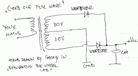
choky said:mebbe is better solution to use both halves ?
CT to ground,and wo diodes (one per half) to + output-just like good ole vacuum rectifier?
in that case your tranny will run colder
I agree with this
better not to leave floating windings
Ok, here is the schematic. I know that there are better ways to do this but Im trying to stay as close to "cloning" the amp as possible. I plan to use 4 FREDS for the fullwave rectifier, each is rated to 12A and 1200V so even if I parallel the winding I won't be heating up the FREDS. Is there a problem with supplying twice the amperage to the amp, or will it only draw what it needs anyway?
Thanks for your help guys.
Milo
edit: spelling
Thanks for your help guys.
Milo
edit: spelling
oops, here it is.
Milo
An externally hosted image should be here but it was not working when we last tested it.
Milo
Hi,
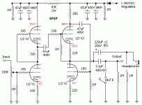
That looks alot like a headphone amp I've seen on Headwize.
Runeight, was that yours?
An anode follower DC coupled into a WCF, nice.
It's very easy to add a bigger cap on the output and a jack so you'll be driving your cans with it as well.
Here's something similar I toyed with a while ago:
Cheers,
That looks alot like a headphone amp I've seen on Headwize.
Runeight, was that yours?
An anode follower DC coupled into a WCF, nice.
It's very easy to add a bigger cap on the output and a jack so you'll be driving your cans with it as well.
Here's something similar I toyed with a while ago:
Cheers,
Attachments
Yeah, its alot like the Morgan Jones on headwize but it differs in a few ways. It is the HAP-03 made by RADII out of China. Its a real POS but if you can get it to work it sounds really nice with Senn HD-600's. Ill be using mostly High ohm cans so I think that I can keep the Output Cap low, if not however Ill just add it to the headphone jack.
Thanks
Milo
Thanks
Milo
Hi,
Someone once advised against the use of HEXFRED diodes, I forgot why exactly but I suppose they were misbehaving.
Either way, if you can't get Schottkys to do the job I'd put some snubber caps across the diodes.
12A is way too much but it'll only hurt the bank, I suppose.
The preamp will only draw whatever it need, so while it's overkill it won't do any damage.
Cheers,
I plan to use 4 FREDS for the fullwave rectifier, each is rated to 12A and 1200V so even if I parallel the winding I won't be heating up the FREDS. Is there a problem with supplying twice the amperage to the amp, or will it only draw what it needs anyway?
Someone once advised against the use of HEXFRED diodes, I forgot why exactly but I suppose they were misbehaving.
Either way, if you can't get Schottkys to do the job I'd put some snubber caps across the diodes.
12A is way too much but it'll only hurt the bank, I suppose.
The preamp will only draw whatever it need, so while it's overkill it won't do any damage.
Cheers,
I thought that was the way it was with current. So do I need to rectify each side of the 220V winding seperatly or is there a way that I can rectify it at the same time and still get 110V with twice the current? Basically do I need to buy 4 more freds? The 12A ones were the same price as the 6A ones and I figured that it will just keep the heat down so what the hey. What would you recommend as snubber caps, type, rating? I know that that is an absurdly broad question but I only know enough to know that the question is broad not what I should use.
He he, at least im not asking "What is the best capacitor ever?"
Thanks,
Milo
He he, at least im not asking "What is the best capacitor ever?"
Thanks,
Milo
A3rd.Zero said:CHOKY
Im interested in that solution but im still to new at this. could you draw me a picture. Ill post it on my refridgerator
Thanks
Milo
Attachments
Hi,
Both the graetz bridge and the FW rectifiers are errr...FW rectifiers.
It's just that the bridge is much more efficient, something you don't want here.
Both need to be filtered adequately just the same.
Cheers,
Thats why you can get away with just using a full wave rather than a bridge rectifier. Or am i missing the point.
Both the graetz bridge and the FW rectifiers are errr...FW rectifiers.
It's just that the bridge is much more efficient, something you don't want here.
Both need to be filtered adequately just the same.
Cheers,
Hi,
Efficient in the sense that it would put out a higher voltage, since you said in your opening post that you only need 110V I assume
there's little point in turning excess voltage into heat.
You'll already see close to 125 VDC max on the filter caps.
Using a FW bridge and NOT grounding the CT would give you twice as much volts in theory.
If that's what you want then that's fine by me.
Cheers,
Why dont i want the more efficient solution?
Efficient in the sense that it would put out a higher voltage, since you said in your opening post that you only need 110V I assume
there's little point in turning excess voltage into heat.
You'll already see close to 125 VDC max on the filter caps.
Using a FW bridge and NOT grounding the CT would give you twice as much volts in theory.
If that's what you want then that's fine by me.
Cheers,
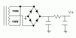
I dont know if the powersupply section calls for delivery of 110V or if that is just the winding of the transformer that they used (the schematic is a little unclear because they never give voltages at test points). If I were to construct a powersupply as below, wouldnt I have basically 110V (not taking into account RMS due to the rectifier or the caps) and just twice the amperage that each side of the winding could produce? Again sorry if I'm totally missing something.
Thanks,
Milo
Thanks,
Milo
Attachments
- Status
- This old topic is closed. If you want to reopen this topic, contact a moderator using the "Report Post" button.
- Home
- Amplifiers
- Tubes / Valves
- Transformer for a tube amp question


