In the UK we are required to use double pole switching for the mains input.
Good to know! Thanks, I will start using DPDT switch for the mains input. In the US all the mains plugs are now polarized so as long as you switch the correct poll it is less of a concern.
It is usual practice to wire the heaters and then using a pair of 100R resistors in series across the 6.3v joining the centre of the resistors to ground. That keeps the maximum peak heater voltage to ground at 3.25 volts.
Jon just help me get me head squarely round this please. I get the centre pair giving the equivalent of a centre tap and referencing that to ground. What guides the choice of 100R? These aren't in circuit right? No current should flow? Ok there's 3.25v across each so if there was a circuit then 32.5mA could flow and dissipate 0.1W - but there's no circuit right?
Could it be any matching pair? Just trying to "grok" it, to coin an old science fiction phrase and show my age.
Sanity check please.
Mains transformer with centre-tapped secondary ... so ...
Primary = 0 - 240 (actually 2 120s in series, but for simplicity)
Secondary = 400 - 0 - 400
The 0v secondary should be grounded, but should it go to mains neutral or mains earth ?
Objectives of grounding that I can see would be;
1) provide a 0v ground reference
2) provide a low-impedance drain for any parasitic capacitance
3) provide a safety earth in case of a short in the secondary winding
For reason 3 I believe it should ground to chassis earth, which connects to mains earth. Any current will trip. Welcome comments confirming I'm right or putting me back on the straight and narrow.
The transformer is actually hidden inside my amp (wooden case) but for complete safety I also connect the transformer case to chassis earth, along with all of the choke cases which are also hidden.
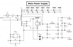
Here, like this (attached)
This connection avoids nasty ground loops that can allow AC ripple moise into the signal chain. The diodes inside the integrated bridge are paralleled in a "69" configuration that doesn't block AC, but the forward voltage floats the chassis from the DC neutral. You still have your safety ground in case there's an internal fault that could put potentially dangerous DC voltages onto the metal parts the end user comes into contact with. The integrated bridge sould have a current rating of at least the rating of the AC mains (usually 20A -- see what your breakers are rated). In case of diode poofage, the 10R resistor maintains contact.
Attachments
The resistor provides a path for low frequency interference current to pass to the enclosure...................In case of diode poofage, the 10R resistor maintains contact.
The capacitor provides a path for high frequency interference current to pass to the enclosure.
The resistor cannot handle Fault Current, it will go "pooffage" long before the Power Rectifier Diodes.
It's the Power Diodes that limit the voltage across the resistor whenever there is a fault current flowing to the PE protected enclosure.
Thanks. My maths is right (good) but my head is all wrong. I'll figure out how that's a circuit.
Thanks for the pointers. One day the penny will drop. Sigh.
The transformer winding and the two resistor (all in series) forms the circuit. The transformer is providing 6.3V ac across the 2 x 100 ohms in series so you get 6.3/200 = 31.5mA. The connection to ground from the junction of the two resistors caries negligible current. It is just there to provide a ‘reference’ voltage.
The transformer winding and the two resistor (all in series) forms the circuit. The transformer is providing 6.3V ac across the 2 x 100 ohms in series so you get 6.3/200 = 31.5mA. The connection to ground from the junction of the two resistors caries negligible current. It is just there to provide a ‘reference’ voltage.
Sorry, need to clarify again. I feel my grokking is almost there, I'm missing a link.
The connection from the junction of the two resistors is to EARTH, not to the secondary 6.3v winding. I'm not seeing the circuit.
Is this because I have a tendency to look at DC rather than AC ? Thinking it through. There's no DC connection between the junction of the resistors and the secondary winding. But for AC, the connection is made via the Earth/Neutral junction (at the mains circuit breaker board), the neutral wire, to the transformer primary and via AC inductance from primary to secondary. Is that right ? Do I have it ?
I really must break that DC habit. I suspect a lot of beginners like me suffer from that ?
Yes there is. The resistors themselves are the connection (both AC and DC) between their junction and the heater secondary.There's no DC connection between the junction of the resistors and the secondary winding.
No, you are clearly very confused.But for AC, the connection is made via the Earth/Neutral junction (at the mains circuit breaker board), the neutral wire, to the transformer primary and via AC inductance from primary to secondary. Is that right ? Do I have it ?
Let's start again. You have a heater winding connected to some heaters, supplying each of them with 6.3V (the heaters are wired in parallel). Now for reasons which I won't bore you with, it is important that the heater circuit not be left to float - it must have a DC reference. The simplest reference to use is 0V or the chassis (these two references may or may not be the same). The simplest way to apply the reference is to ground one side of the heater supply. Note that we are not talking of a safety ground to the incoming mains ground, but a circuit ground which could be the chassis or the star point or some point on the ground bus.
Grounding one side of the heater supply leaves the other side at 6.3V AC. Sometimes this can create hum, especially in very sensitive circuits or badly built circuits. It may be better to ground the 'centre' of the heater supply, so instead you get two antiphase 3.15V wires. This halves the hum from one wire and may to some extent cancel even that with antiphase hum from the other wire. Better quality mains transformers will provide a centre tap on the 6.3V winding, so you just ground the CT. If not present, you can create an artificial centre-tap with a pair of resistors.
Take two 100R resistors. Join them in series. Put the two loose ends on each side of the 6.3V heater wiring. You have 200R across 6.3V AC - you can work out the dissipation in each resistor. Ground the junction. This establishes the heater reference - it is equivalent to grounding the heater secondary CT via a 50R resistor.
Be aware that some people will advise you to 'ground' an audio heater circuit via something like a 0.01uF capacitor. This is daft. It does not provide a reference voltage. It has almost no effect in an audio circuit. It does have one useful effect though: it warns you that you can safely ignore almost any electronics advice from this person.
Thank you DF96. That's clear - and is actually where I started from. I managed to throw myself off course during this thread. I started off asking about the 0v secondary winding 400-0-400 and got ...
The centre winding should go to the chassis grounding point and Ground means Earth definitely NOT neutral!
I then diverted to asking about filament grounding and got ...
It is usual practice to wire the heaters and then using a pair of 100R resistors in series across the 6.3v joining the centre of the resistors to ground.
I combined those together and got (in my head) 2 x 100R, junction connected to Earth, not ground.
Thanks for clearing up. I know I sound very confused, and grounding is my weakest area, but I spend a lot of time clarifying, researching and asking questions so I come across a bit slow occasionally.
Be aware that some people will advise you to 'ground' an audio heater circuit via something like a 0.01uF capacitor. This is daft. It does not provide a reference voltage. It has almost no effect in an audio circuit. It does have one useful effect though: it warns you that you can safely ignore almost any electronics advice from this person.
An advice bypass cap

> In the US all the mains plugs are now polarized...
In my old kitchen, 60% of the polarized outlets were wired *wrong*.
Also none of the 3-pin outlets had ground wires. (This can be perfectly legal; though this wasn't.)
In my "new" 1983 house over 90% of outlets are polarized correctly; but many wires were/are loose at the outlet and even in the fusebox.
A bad connection in the White wire will make all upstream "Neutral" HOT through any connected loads. Been bit by that.
On a thread in the PS section we have a guy who apparently does not have any neutral power conductor- all loads fed hot-hot on 3-phase legs, plus a Protective Earth. (This is so odd that the thread gets off-track.)
NEVER EVER think you know where "Neutral" is!
If it isn't clearly and surely GREEN(bare), it is "HOT".
Your green power wire should go to chassis as direct as possible. Codes prefer a dedicated bold so you do not have to disturb this to repair other connections.
There should be NO current in power green except in a breakdown. You don't "aim" anything inside your amp "at" power ground. It is possible (if difficult) to wire the whole amp "floating" from ground. Usually some point on power and audio common connects to chassis. Often an input jack.
__________________
Audio "grounding" must not conflict with the Safety grounding.
Your PT and rectifier SHOULD go direct to First Filter Cap. Your major load (power tubes) should return here. Other stages eventually get here but are less critical as long as the BIG rectifier pulses and large tube thumps return to first cap.
I disagree with part of this. The output stage ground, like the rest of the circuit, should come from the PSU output ground - not the reservoir cap ground as you appear to say. Otherwise the output stage is using a different signal reference from the rest of the circuit.PRR said:Your PT and rectifier SHOULD go direct to First Filter Cap. Your major load (power tubes) should return here. Other stages eventually get here but are less critical as long as the BIG rectifier pulses and large tube thumps return to first cap.
- Status
- This old topic is closed. If you want to reopen this topic, contact a moderator using the "Report Post" button.
- Home
- Amplifiers
- Power Supplies
- Mains transformer Secondary 0v grounding