Dear all
After having finished my two bi-amp monoblocks with two quads of 6V6s on each monoblock, i think about a new project. I still have some tubes left, 6SJ7, 6SN7 and two matched quads of 6L6GC.
I would like to make two monoblocks with a 6SJ7 voltage amp, 6SN7 LTP and a quad of 6L6GC in push pull, run on approx. 400V on plate and little less on screen.
- as power tranny I would use a Hammond 378CX (400-0-400v 534mA, 6.3v 6A to heat 6SJ7 and 6SN7)
- for heater power of 6L6 quad a Hammond 266S6 (6.3v 10A)
- for rectifier heaters a Hammond 266S6 (6.3V 10A with a 0.2R/10W resistor to get down to 5V), since there are no 5V rectifier trannies available for 220V primary - or does anybody knows a 5V 8-10A rectifier heater tranny with 220-240V primary? Or go solid state rectification?
- Hammond chokes 193P 5H/500mA and 193Q 10H/500mA
The big question for me is the OPT, Hammond only has a 120W 1900ct OPT for push pull, they say it works with a quad of 6L6 on their web site.
Are there any suggestions for other OPTs with approx 120W and 3300ct (i would like trannies with bells for visible mounting).
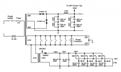
Attached you will find a schematic for what I am planning. The LPT stage is exactly the same as I used it in my 6V6 quad amp. The quad stage has just adapted cathode resistors.
I would appreciate a review, especially of the 6SJ7 stage and the 6L6 quad stage cathode resistors.
As soon as I know that the 6SJ7 stage is correct, I want to add a feedback loop with adjustable feedbach to the 6SJ7 (proposed by rojoknox when dicussing my 6V6 amp).
Thanks a lot for your support.
Thomas
After having finished my two bi-amp monoblocks with two quads of 6V6s on each monoblock, i think about a new project. I still have some tubes left, 6SJ7, 6SN7 and two matched quads of 6L6GC.
I would like to make two monoblocks with a 6SJ7 voltage amp, 6SN7 LTP and a quad of 6L6GC in push pull, run on approx. 400V on plate and little less on screen.
- as power tranny I would use a Hammond 378CX (400-0-400v 534mA, 6.3v 6A to heat 6SJ7 and 6SN7)
- for heater power of 6L6 quad a Hammond 266S6 (6.3v 10A)
- for rectifier heaters a Hammond 266S6 (6.3V 10A with a 0.2R/10W resistor to get down to 5V), since there are no 5V rectifier trannies available for 220V primary - or does anybody knows a 5V 8-10A rectifier heater tranny with 220-240V primary? Or go solid state rectification?
- Hammond chokes 193P 5H/500mA and 193Q 10H/500mA
The big question for me is the OPT, Hammond only has a 120W 1900ct OPT for push pull, they say it works with a quad of 6L6 on their web site.
Are there any suggestions for other OPTs with approx 120W and 3300ct (i would like trannies with bells for visible mounting).
Attached you will find a schematic for what I am planning. The LPT stage is exactly the same as I used it in my 6V6 quad amp. The quad stage has just adapted cathode resistors.
I would appreciate a review, especially of the 6SJ7 stage and the 6L6 quad stage cathode resistors.
As soon as I know that the 6SJ7 stage is correct, I want to add a feedback loop with adjustable feedbach to the 6SJ7 (proposed by rojoknox when dicussing my 6V6 amp).
Thanks a lot for your support.
Thomas
Attachments
Last edited:
Thomasweissbach,
There is a couple errors in you schematic. One, the 6SQ7 is a triode and not a pentode as shown. The 6SQ7 also contains a couple of diode normal used for a detector which will not hurt anything but should be disabled. Second, the filaments for the two 5U4's should be in parallel and not series if being powered via a 6.3v winding with a dropping resistor.
A couple of other recommendations are to add a dedicated grid leak resistor to the control grid of the 6SQ7 and ground. This will keep the tube bias assured even if pot gets a little dirty over time and itermittently goes open. Also, do not ground both ends of the shield cable going to the input connector. This will help assure no ground loop currents at the front end.
Mickeystan
Last edited:
Dear all,
you'right, there are some copy paste mistakes in the schematic which I took from my other project...
I want to use a 6SJ7 as voltage amp, the 6SQ7 on the schematic is wrong.
I have changed the filament supply of the 5U4GB to parallel, as proposed by Mickeystan and changed the grounding od the shielded input cable.
The cap on B+ is now star grounded.
Concerning kwards input of the lower output of the 6L6 quad, could it be increased by higher B+? This would mean using a pair of 5AR4 instead of the 5U4GB, this would give some extra power on B+.
How should the set up be to get lets say 40W from a push pull pair and around 80 from the quad?
Thanks a lot for your inputs.
Thomas
Attachments
If you don't mind a little sand in your amp, you can check out George's powerdrive experiments with a pair of 6L6GCs producing 90W in AB2: 500V anode, 400V g2, 3k3 load. Still 50W in triode mode AB2.
Universal PP Driver Board | Tubelab
Universal PP Driver Board | Tubelab
Why use an extra transformer for heating the 6L6s when the main PT has enough capacity?
For what i have read about Hammonds, they need to be properly loaded or they'll put out more voltage.
Also, when you go for vacuum rectification, make sure the heater winding for the 5U4s or GZ34s has a DC rating as well. The winding will have the full rectified dc while the core is grounded.
For what i have read about Hammonds, they need to be properly loaded or they'll put out more voltage.
Also, when you go for vacuum rectification, make sure the heater winding for the 5U4s or GZ34s has a DC rating as well. The winding will have the full rectified dc while the core is grounded.
How should the set up be to get lets say 40W from a push pull pair and around 80 from the quad?
This would be achieved better with fixed bias. Have some 450...480 V as +B and 2k5 to 3k3 OPT.
I have built several 5881 and 807 UL PP amplifiers and got 35...40 W with 450 V +ub with fixed bias and 6k6 OPT.
I would also leave the second choke away and use some 220 uF to 330 uF filter capacitance after the choke.
Here's what you could do:
The above will deliver maybe 75 to 80 watts output as seen at the speaker terminals (if your screen supply is stiff). But it will take some effort and skill to pull it off:
The output stage will be relatively easy to drive given a 450V B+ rail, but double check that your inverter can cleanly swing the voltage it needs to drive the output stage. Also I'd increase the size of the decoupling cap in this stage to 0.22 uF.
All of this is squeezing about all there is out of the little 6L6s, given a conventional class AB-1 output stage and the use of these particular Hammond outputs.
- Use Hammond 1650T output transformers.
- Use a matched quad of 6L6-GC tubes configured in push pull, class AB1.
- Connect output stage in pentode mode, with 400V on screens.
- Set plate voltage at 450V.
- Use fixed bias, with -42V bias delivered to grids. This will idle tubes at 19 watts static plate dissipation per tube (about 40 mA per tube), which is about 60% of design center max value. Can go a little higher on bias current if you want.
The above will deliver maybe 75 to 80 watts output as seen at the speaker terminals (if your screen supply is stiff). But it will take some effort and skill to pull it off:
- You need a beefy B+ supply that can deliver upwards of 600 mA DC under max power conditions. I'd use silicon rectification for this job.
- You need a stiff screen supply.
- You need a negative bias supply that is centered around -40V but with some variability on both sides so you can dial in the exact bias you want. Separate bias adjustment per tube would be more ideal, or even a bias/balance scheme, even if you used matched tubes.
The output stage will be relatively easy to drive given a 450V B+ rail, but double check that your inverter can cleanly swing the voltage it needs to drive the output stage. Also I'd increase the size of the decoupling cap in this stage to 0.22 uF.
All of this is squeezing about all there is out of the little 6L6s, given a conventional class AB-1 output stage and the use of these particular Hammond outputs.
Last edited:
Hi kward and artosalo
I will leave away the second choke and replace it with some additional uF (what type of cap is proposed here?), which will give some more voltage and replace the 5U4GB with 5AR4 which will give additional voltage and approx. 500mA (nearly the max of what the tranny delivers).
Alternatively a silicone rectifier (any schematic for such a solution?).
How would I best achieve a -40V bias supply for the 6L6s?
Thomas
Last edited:
I adapted the schematic
- with a silicon rectifier and negative bias for the 6L6 grids (are the proposed diodes and the schematic ok?) and changed the resistor in front of B1 to get down to approx. 300V
- removed the additional filament trannys
- removed the 5H choke and increased the caps (enough uF?)
- what I did in addition: i changed the resistors on the 6SJ7 (anode new 100k (before 220k), grid new 400k (before 1M) and cathode to 700R made of 200R poti and 500R (before 1k) to get more gain
- And i added an adjustable negative feedback (to the whiper of the 200R poti, as well as I lifted the cathode bypass cap to this point). Feedback resistor 10k and resistor bypass cap 180pF
Do I need to remove or change the grid resistors of the 6L6 (currently 270k) when using fixed bias with -42V?
I hope this works
Thomas
Attachments
Last edited:
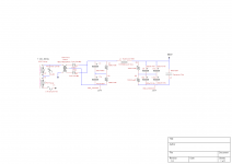
Because you're using a 400-0-400 secondary, it will deliver about 560V DC unloaded. So to obtain the voltage rating on the power supply filter caps you will need, it is customary to "stack" capacitors with voltage equalizing resistors between them. The example below shows two 350V caps stacked vertically, so the voltage rating is doubled to 700V, but the capacitance is halved, to 110 uF.
Also the example shows how you would do silicon rectification in this setup. If you use standard 1000V PIV diodes, two UF4007 diodes connected in series per leg of the output transformer will be needed, because of the use of the 400-0-400 transformer, it will create about 1200V difference between the anode and cathode of the diode.
The Hammond 378CX does not have a bias tap off of the high voltage winding, otherwise you could just use it directly for your bias supply. Since it is not available, you will need to obtain the bias voltage from some other means, such as another stand alone transformer. You need about -42V delivered to the grids, which means you need at least (say) -60 VDC raw bias voltage so that you can filter down to -42V. So, you could just purchase a separate small transformer with a 50V secondary. Almost no current will flow, so pretty much any transformer that delivers a 50 VAC secondary will work. But anything between say 50 VAC and 100 VAC secondary will work just fine.
Here's an example that puts all of these ideas together. This is only one of many ways to do the bias supply. Note in the case shown in the example, I used a small filament transformer run backwards to obtain the bias voltage (because it was inexpensive).
(Side note: Above about 30 watts output, you can see that things are necessarily more complex.)
Edit: I typed most of this before I saw your last post. You could obtain the bias voltage the way you are showing by tapping off of one leg of the high voltage winding. Some refinement of that approach would be necessary though. Personally I prefer the stand-alone filament transformer approach, but that is just my preference.
Attachments
Last edited:
I'm actually using that transformer in a stereo KT120 triode amp right now. Here is what I did and the voltage you will most likely be close to. My line voltage here is pretty much exactly 120V.
Ooops... I get 543 volts with ~220mA current draw not 560V.
Ooops... I get 543 volts with ~220mA current draw not 560V.
Attachments
Last edited:
The 1.9K/quad, 4K/pair, loading is for Guitar amp. And for Fixed bias. Where idle current is much less than full-power current.
The 1.9K/quad, in a self-bias design (current hardly changes idle to loud), at say 540V of B+ and 500V across the tubes, must idle near 250 Watts/quad or 60W/bottle. With 30W "6L6", this aint happy. You want to come down near 350V across the tubes, under 400V of B+. Which is a major drop from a 400Vrms 560V peak power transformer.
With that PT and self-bias you probably want to be near 8K/pair 4K/quad.
Alternatively do fix-bias and 4K/pair. Even then, 540V is a lot by 6L6GC ratings (especially G2).
Yes, I would much rather see you build your amp with the proper power transformer. The current situation with the 378CX is going to be running the 6L6s on the ragged edge. If you can stick to something around 450V plate, 400V grid, the 6L6s will be happier.
Just an idea--convert your design over to a pair of KT88s or 6550s. A whole new design, but the HV winding on the 378CX would be just about ideal for a pair of tubes in that scenario. Run in UL, a pair of KT88s, fixed biased, powered by the 378CX would deliver maybe 70 watts output with a 4.3K output transformer.
Just an idea--convert your design over to a pair of KT88s or 6550s. A whole new design, but the HV winding on the 378CX would be just about ideal for a pair of tubes in that scenario. Run in UL, a pair of KT88s, fixed biased, powered by the 378CX would deliver maybe 70 watts output with a 4.3K output transformer.
It does not necessarily need to be the 378CX from Hammond.
All I have at the moment is the tubes, and I want to work with these... I do not want to buy another set of tubes when two quads of 6L6s are around.
What about another power tranny with lower center tapped secondary?
All I have at the moment is the tubes, and I want to work with these... I do not want to buy another set of tubes when two quads of 6L6s are around.
What about another power tranny with lower center tapped secondary?
- Status
- This old topic is closed. If you want to reopen this topic, contact a moderator using the "Report Post" button.
- Home
- Amplifiers
- Tubes / Valves
- 6L6 quad push pull monoblock project