I'm still studying tube amp design and you all have been great answering what may seem to be basic questions thus far. Thank you for your responses.
As I'm trying to learn more about SE designs, would you mind helping answer a few more questions.
I numbered most of the components on this newly attached schematic. Would you mind filling in any blanks I have relating to the name and purpose of each component and validating any that have a question mark? Also, correct me if I have any wrong thus far, this was my stab in the dark:
1 - Variable pot for volume control (voltage divider on input)
2 - Grid stopper resistor (not completely sure of purpose?)
3 - Plate resistor (drop voltage to appropriate level on resistor)
4 - Cathode resistor (set bias relative to grid?)
5 - coupling capacitor (keep AC off following stage)
6 - not really sure other than it sets up a voltage divider for input to next tube?
7- Grid stopper resistor (not completely sure of purpose)
8 - ?
9 - Cathode resistor (?)
10 - Cathode resistor (?)
11 - ?
12 - Grid stopper resistor (?)
13 - Cathode resistor (?)
14 - Cathode bypass cap (?)
15 - ?
16 - ?
17 - Screen bias (Sets screen voltage via zener values)
18 - ?
19 - ?
20 - ?
21 - NFB resistor (sets amount of feedback making it to input - buy why to cathode of 1st tube instead of to grid?)
Thanks,
Lilstripe
Attachments
1 - Variable pot for volume control (voltage divider on input)
Yes
2 - Grid stopper resistor (not completely sure of purpose?)
This helps break up any high frequency parasitic circuits by de-Q-ing these circuits formed by device/stray reactances.
3 - Plate resistor (drop voltage to appropriate level on resistor)
This is a passive plate load, without which there would be no voltage gain.
4 - Cathode resistor (set bias relative to grid?)
Yes
5 - coupling capacitor (keep AC off following stage)
Yes
6 - not really sure other than it sets up a voltage divider for input to next tube?
This is the DC return reference resistor. It provides a light AC load while referencing the grid to DC ground, otherwise, the grid would float and this stage wouldn't work right. There should be very little DC dropped across it.
8 - ?
Another grid stopper
9 - Cathode resistor (?)
Yes
10 - Cathode resistor (?)
Yes
11 - ?
DC grid reference
12 - Grid stopper resistor (?)
Yes
13 - Cathode resistor (?)
Yes
14 - Cathode bypass cap (?)
Yes. For power stages that use cathode bias, this is essential if you're not to lose a helluvalot of power and/or drive up the rp.
15 - ?
Screen bypass capacitor. Power pents work best if the screen(s) are returned to AC ground with a Lo-Z connection. Here, the capacitor does double duty it also bypasses the noise the Zeners will produce
16 - ?
Ballast resistor to limit the current through the Zeners
17 - Screen bias (Sets screen voltage via zener values)
Zeners used as a parallel screen voltage regulator.
18 - ?
19 - ?
20 - ?
An AC bypassed voltage regulator that floats the heaters above DC ground. This helps with noise reduction, especially in cases where cathodes are far removed from AC ground. Red hot aluminum oxide acts more like a lightly N-doped semiconductor than an insulator. This can leak AC into the signal chain. Making the heaters positive reverse biases that parasitic diode.
21 - NFB resistor (sets amount of feedback making it to input - buy why to cathode of 1st tube instead of to grid?)
The cathode is the "invert" input. You could return it to the input, but that would reduce the input impedance, perhaps enough to overload whatever's driving the input. it is sometimes done, bit not very often.
Yes
2 - Grid stopper resistor (not completely sure of purpose?)
This helps break up any high frequency parasitic circuits by de-Q-ing these circuits formed by device/stray reactances.
3 - Plate resistor (drop voltage to appropriate level on resistor)
This is a passive plate load, without which there would be no voltage gain.
4 - Cathode resistor (set bias relative to grid?)
Yes
5 - coupling capacitor (keep AC off following stage)
Yes
6 - not really sure other than it sets up a voltage divider for input to next tube?
This is the DC return reference resistor. It provides a light AC load while referencing the grid to DC ground, otherwise, the grid would float and this stage wouldn't work right. There should be very little DC dropped across it.
8 - ?
Another grid stopper
9 - Cathode resistor (?)
Yes
10 - Cathode resistor (?)
Yes
11 - ?
DC grid reference
12 - Grid stopper resistor (?)
Yes
13 - Cathode resistor (?)
Yes
14 - Cathode bypass cap (?)
Yes. For power stages that use cathode bias, this is essential if you're not to lose a helluvalot of power and/or drive up the rp.
15 - ?
Screen bypass capacitor. Power pents work best if the screen(s) are returned to AC ground with a Lo-Z connection. Here, the capacitor does double duty it also bypasses the noise the Zeners will produce
16 - ?
Ballast resistor to limit the current through the Zeners
17 - Screen bias (Sets screen voltage via zener values)
Zeners used as a parallel screen voltage regulator.
18 - ?
19 - ?
20 - ?
An AC bypassed voltage regulator that floats the heaters above DC ground. This helps with noise reduction, especially in cases where cathodes are far removed from AC ground. Red hot aluminum oxide acts more like a lightly N-doped semiconductor than an insulator. This can leak AC into the signal chain. Making the heaters positive reverse biases that parasitic diode.
21 - NFB resistor (sets amount of feedback making it to input - buy why to cathode of 1st tube instead of to grid?)
The cathode is the "invert" input. You could return it to the input, but that would reduce the input impedance, perhaps enough to overload whatever's driving the input. it is sometimes done, bit not very often.
Since we are having so much fun with this thread, anything you would change about the original design?
You could use VR (voltage regulator tubes) instead of zeners. Same function, but colorful.
Sheldon
You could use VR (voltage regulator tubes) instead of zeners. Same function, but colorful.
Yes, but 10 uF cap in parallel would make a good relaxation oscillator. ;-)
Yes, but 10 uF cap in parallel would make a good relaxation oscillator. ;-)
Well, yes. Every alternative approach requires applying the new device within its working specifications.
Well, yes. Every alternative approach requires applying the new device within its working specifications.
And of course, for that we refer to the data sheet: https://frank.pocnet.net/sheets/127/0/0B2.pdf
See figure 2 for series operation.
Sheldon
Hi,
I built this amp, and have big trouble with hum. I built several tube's amps before, but never had a big problem like this.
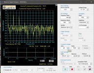
I can't get hum under -65dB (e.g. on PCL86 SE I have -95dB). I re-arranged ground connections, filaments wiring, add some capacitors etc. but without change. Does anybody built this, and have plan for grounding please? I still think, that something with ground wiring is bad. Thank you.
This is the best result I achieved after last ground connections re-arrangement.
I built this amp, and have big trouble with hum. I built several tube's amps before, but never had a big problem like this.
I can't get hum under -65dB (e.g. on PCL86 SE I have -95dB). I re-arranged ground connections, filaments wiring, add some capacitors etc. but without change. Does anybody built this, and have plan for grounding please? I still think, that something with ground wiring is bad. Thank you.
This is the best result I achieved after last ground connections re-arrangement.
Attachments
")
Ground the control grid on the 807. See what ripple you get now. Unground the 807 control grid.
Ground (short across) the 220k grid resistor of the second stage. See what ripple you get now. Remove that ground (short).
Do you see, we are troubleshooting what stage the hum is mainly coming from.
Chokes also can couple magnetic fields to the output transformers.
The capacitors in the B+ after the chokes are far less than I normally use.
Maybe there is too much ripple.
I use a local ground loop in B+: Secondary center tap, to first filter cap negative, from there to the 2nd filter cap negative (2 in this case), and only after those wires, you can connect to the rest of the circuit grounds. Keep those first leads short, and away from other stage wires (large impulse currents can couple magnetically to other wires.
Check the ripple voltage on each stage of the amp. You have to calculate each contribution of those ripples to the hum you get.
Not the exact quantities, but just to illustrate an Example:
25mV ripple at the B+ to the 807 OPT primary, 807 Pentode plate resistance of 10,000 Ohms, OPT primary 5,000 Ohms.
The ripple across the 5,000 Ohm secondary would be 25mV (5,000/(10,000 + 5,000)) =
8.33mV.
A 5,000 Ohm primary to 8 Ohm secondary has a 25:1 turns ratio. Root (primary impedance/secondary impedance) = turns ratio.
8.33mV/25 = 0.333mV (333uV) at the 8 Ohm tap.
But if the output stage B+ ripple there is 250mV, you now have 3.33mV ripple at 8 Ohms.
B+ ripple in the earlier stages is amplified by the gain of those stages.
More calculations.
Be very sure that the filament secondary that has the resistive divider coming from B+, needs to have the bypass cap, and it needs to power the filament of the Top Tube in the SRPP stage. That is to reduce the filament to cathode voltage which can cause hum, and can cause leakage of the Top Tube which can change the circuit's correct operation.
Good luck.
You have re-activated a very old thread (because this is the amp you have).
PS I did not read through the whole thread, just the schematic in post 1, and your post asking for help with the hum.
Last edited:
- Status
- This old topic is closed. If you want to reopen this topic, contact a moderator using the "Report Post" button.
- Home
- Amplifiers
- Tubes / Valves
- SE807 Triode Dick Amplifier Questions