In a phono stage the evil is the noise, if you want a low noise version, ala Allen Wright
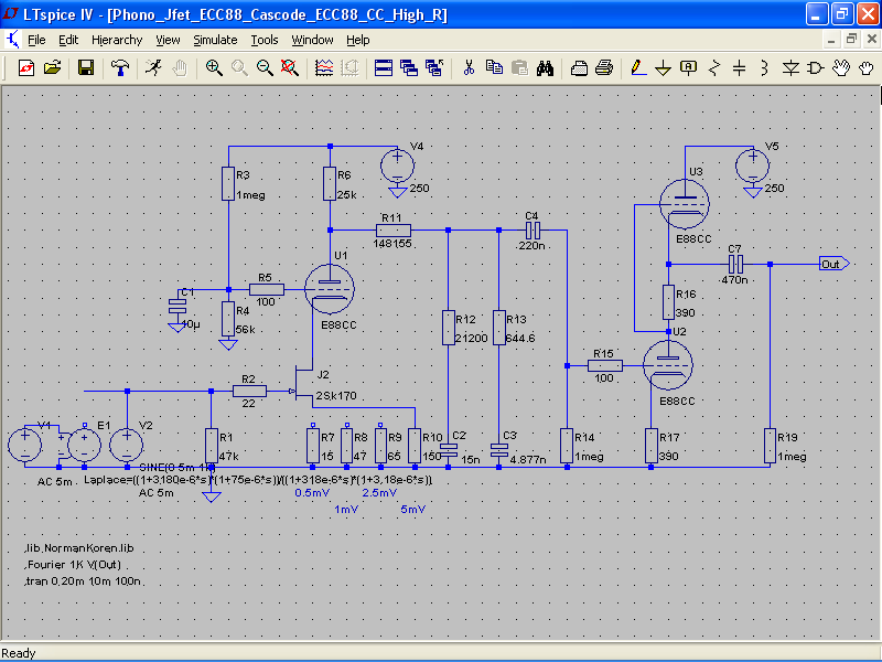
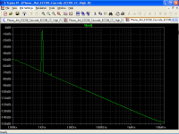
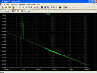
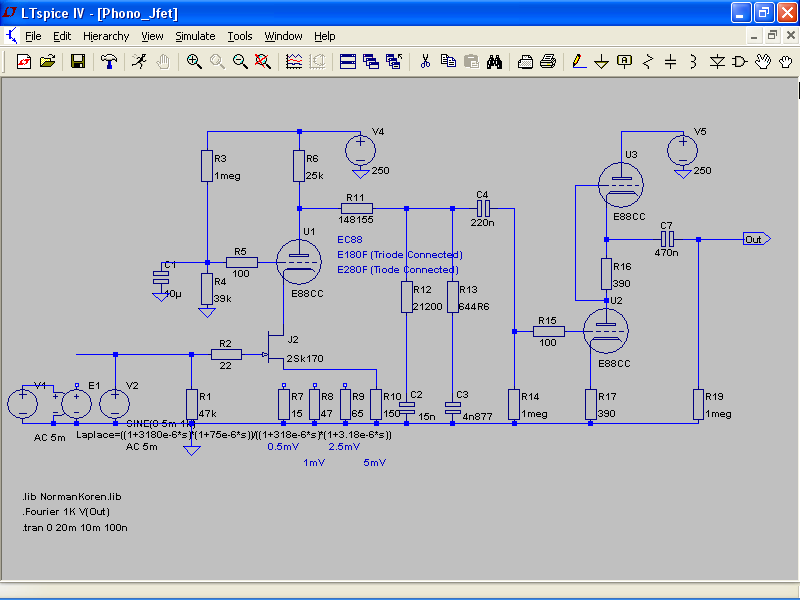
THD is about 0.02%, mostly 2nd harmonic

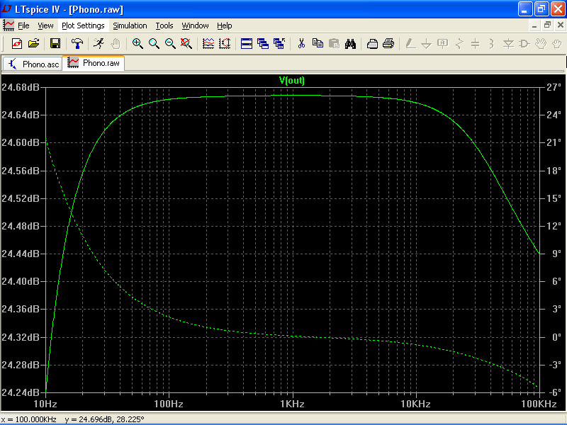
Frequency response is about ±0.1dB from 15Hz to 20KHz, note that resistors and capacitors of EQ must be trimmed.

Here is included the missing constant 3.18µs, LPs are recording this way.
Output impedance is <2K, note that you can adjust input sensitivity from 0.5mV to 5mV, then you can use MM and MC cartridge.
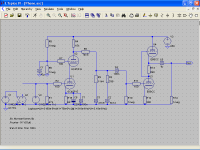
I am building this one for myself, as upper triode of the cascode you can use E88CC, EC88, E180F (triode connected), 6C45P...etc.
THD is about 0.02%, mostly 2nd harmonic
Frequency response is about ±0.1dB from 15Hz to 20KHz, note that resistors and capacitors of EQ must be trimmed.
Here is included the missing constant 3.18µs, LPs are recording this way.
Output impedance is <2K, note that you can adjust input sensitivity from 0.5mV to 5mV, then you can use MM and MC cartridge.
I am building this one for myself, as upper triode of the cascode you can use E88CC, EC88, E180F (triode connected), 6C45P...etc.
Attachments
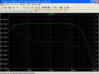
Frequency response is about ±0.1dB from 15Hz to 20KHz
Erratum
RIAA deviation is about ±0.01dB from 15Hz to 20KHz.
Last edited:
Hmm I smell some semiconductor-phobia. 
An LED sounds much better than an electrolytic capacitor and the JFET is transparent, anyway here is my last try.
I found a model for the 6C45P, do not know its accuracy.

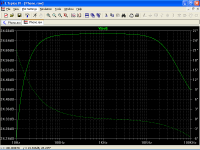
THD is about 0.05% mostly 2nd harmonic

RIAA deviation is about ±0.1dB
Now, the missing constant 3.18µs is added, output impedance is the same, <2K and if you want to lowering it just bypass the bottom resistor, distortion will increase though.
You can trim resistors and capacitors with a cheap multimeter and a pocket calculator, e.g.
R8 = 74K5 ≈ 75K // 10 M
If you use the Salas shunt regulator, you must connect each section with two wires and other two wires for ground, see details in his thread.
Good luck!
An LED sounds much better than an electrolytic capacitor and the JFET is transparent, anyway here is my last try.
I found a model for the 6C45P, do not know its accuracy.
THD is about 0.05% mostly 2nd harmonic
RIAA deviation is about ±0.1dB
Now, the missing constant 3.18µs is added, output impedance is the same, <2K and if you want to lowering it just bypass the bottom resistor, distortion will increase though.
You can trim resistors and capacitors with a cheap multimeter and a pocket calculator, e.g.
R8 = 74K5 ≈ 75K // 10 M
If you use the Salas shunt regulator, you must connect each section with two wires and other two wires for ground, see details in his thread.
Good luck!
Attachments
Last edited:
Why did you change Zout from 6k to 54k ? It is 6k not 54k !
Mona
I have performed the tests with the components of the modification, the circuit has become unstable and very noisy, however I have made measurements and the response from 1khz onwards drops sharply.
Many thanks Ketje for your help I am very grateful.
At this point I do not know what to do and leave it like this, I think this preamplifier does not give more.
Many thanks popilin you have done a great job with this preamplifier.
I am thinking of leaving the 6c45p tubes, I think they are not very good tubes if you are looking for something really good, instead this circuit with E88CC looks very good and I am thinking of doing it, you can give me the schematics to be able to make this preamplifier, in The image you have put does not look very clear some components.
I am very grateful for the circuit you have done for me.
I am thinking of leaving the 6c45p tubes, I think they are not very good tubes if you are looking for something really good, instead this circuit with E88CC looks very good and I am thinking of doing it, you can give me the schematics to be able to make this preamplifier, in The image you have put does not look very clear some components.
Many thanks popilin you have done a great job with this preamplifier.
I am thinking of leaving the 6c45p tubes, I think they are not very good tubes if you are looking for something really good, instead this circuit with E88CC looks very good and I am thinking of doing it, you can give me the schematics to be able to make this preamplifier, in The image you have put does not look very clear some components.
I am very grateful for the circuit you have done for me.
Nothing to thank, we are here to help each others.
6C45P has very high transconductance and it will oscillates if you let it, in your circuit there are no grid stoppers, this is an invitation to oscillate.
Here is the circuit, I did reduce a little bit the grid voltage of upper triode of the cascode, so the JFET will work between about 10V and 15V depending on source resistor.
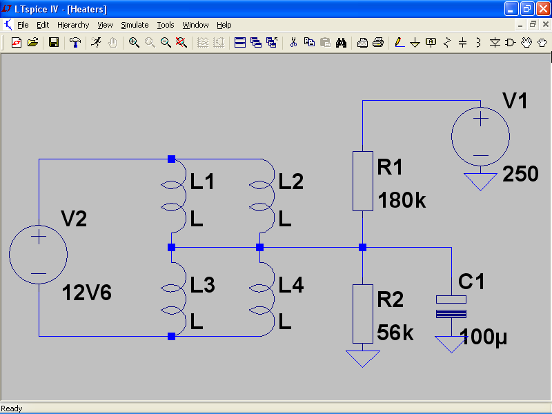
Heater voltage elevation should be about 60V or a little bit less.
Hints
i) An E88CC on upper triode of the cascode could be a little unconvenient (waste one section), here you can use any low noise triode or triode connected pentode.
ii) E88CC has two "different" sections, see datasheet to connect the correct one as upper triode and bottom triode respectively (both on cascode and SRPP stage) this is more clear in ECC88 datasheet.
iii) Stray capacitances make very difficult to achieve ±0.01dB RIAA deviation, so trim resistors and capacitors with the highest resolution of your multimeter and it will be enough to obtain at least ±0.1dB, no need to be a fanatic here, nevertheless channel to channel you must trim them as close as possible.
iv) Beware of fakes 2SK170, they should be matched, BL grade or better V grade.
You can also use the 2SK369, it is even better but difficult to obtain.
v) R1=47K is intended for MM cartridge, if you use an MC cartridge you must lower it.
vi) R6 should be 25K/5W wirewound, also trimmed channel to channel, four 100K/2W in parallel should also work fine.
vi) If you make some measurements, be sure to use the inverse RIAA on the input, anyway if you trim resistors and capacitors close enough, the circuit would work fine, I have no a decent signal generator, never do such measurements and my phono stages sound very very good.
6C45P has very high transconductance and it will oscillates if you let it, in your circuit there are no grid stoppers, this is an invitation to oscillate.
Here is the circuit, I did reduce a little bit the grid voltage of upper triode of the cascode, so the JFET will work between about 10V and 15V depending on source resistor.
Heater voltage elevation should be about 60V or a little bit less.
Hints
i) An E88CC on upper triode of the cascode could be a little unconvenient (waste one section), here you can use any low noise triode or triode connected pentode.
ii) E88CC has two "different" sections, see datasheet to connect the correct one as upper triode and bottom triode respectively (both on cascode and SRPP stage) this is more clear in ECC88 datasheet.
iii) Stray capacitances make very difficult to achieve ±0.01dB RIAA deviation, so trim resistors and capacitors with the highest resolution of your multimeter and it will be enough to obtain at least ±0.1dB, no need to be a fanatic here, nevertheless channel to channel you must trim them as close as possible.
iv) Beware of fakes 2SK170, they should be matched, BL grade or better V grade.
You can also use the 2SK369, it is even better but difficult to obtain.
v) R1=47K is intended for MM cartridge, if you use an MC cartridge you must lower it.
vi) R6 should be 25K/5W wirewound, also trimmed channel to channel, four 100K/2W in parallel should also work fine.
vi) If you make some measurements, be sure to use the inverse RIAA on the input, anyway if you trim resistors and capacitors close enough, the circuit would work fine, I have no a decent signal generator, never do such measurements and my phono stages sound very very good.
Attachments
Last edited:
Thank you very much always, as soon as I have all the components I will keep you informed of the evolution of the phono stage
OK. In the meantime if I can help, just say it.
Although I said that I was going to carry out the project of Mr. popolin, that wanted to insist with this phono preamplifier, (I always am time to realize it).
I show the changes made.
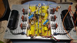
I have been working with 6s45p-e and 5751 tubes, although the final tubes are 6s15p and ecc808.
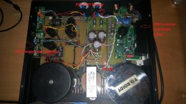
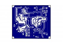
Photos of the prototype.
Any Suggestions?.
I show the changes made.
I have been working with 6s45p-e and 5751 tubes, although the final tubes are 6s15p and ecc808.
Photos of the prototype.
Any Suggestions?.
Attachments
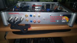
buzzing indomitable
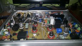
Hello friends, I made this phono stage and the truth is that I am happy with its sound.
But the hums I am not able to solve, I think that these hums are not because of the ground.
I say this because the hum is magnified, for example when my transcendent sound preamplifier is close by, only at 30 centimeters the hum of the transformer can be heard perfectly.
I have attached two audios, one with the MC input and the other with the MM input, and being far from any nearby transformer and with the amplifier's volume at maximum is when it emits less noise.
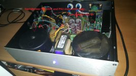
As you can see, the PSU is separate.
Can somebody help me?.
Thanks in advance
Hello friends, I made this phono stage and the truth is that I am happy with its sound.
But the hums I am not able to solve, I think that these hums are not because of the ground.
I say this because the hum is magnified, for example when my transcendent sound preamplifier is close by, only at 30 centimeters the hum of the transformer can be heard perfectly.
I have attached two audios, one with the MC input and the other with the MM input, and being far from any nearby transformer and with the amplifier's volume at maximum is when it emits less noise.
As you can see, the PSU is separate.
Can somebody help me?.
Thanks in advance
Attachments
Is that with the cover on? What happens if you short the inputs? What about tube screens, Covers? If you have a scope where in the circuit are you picking it up? My gut feeling from what you are saying is that it is environmental, screening or layout issues. It will be interesting to see what the pro's have to say. Let us know when you get it figured out.
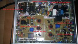
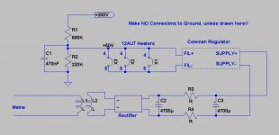
""The negative of the filament supply is connected to general ground? No, through a Bias""
??
Walter
Yes attached explanatory image
Attachments
- Status
- This old topic is closed. If you want to reopen this topic, contact a moderator using the "Report Post" button.
- Home
- Amplifiers
- Tubes / Valves
- Improvements in this riaa tube