Or bigger? You want the PS noise injection to go down to the frequency of mains disturbances, which is near DC. Or make coupling caps smaller so the disturbance can't propagate to the next stage.wicked1 said:My first guess is the ps noise injecting cap.. I'll make it a lot smaller.
Ok, I'll admit I'm not completely clear on how the aikido works... My thought was that it's taking that fraction of a second power fluctuation, and stretching it out to a several second event.. a smaller cap would maybe let that cycle complete faster. I haven't even looked at the schematics or really put a lot of thought in to it yet.. I just noticed the problem a couple of days ago, and then took the pre out of the loop.
I think it's got a voltage divider in that part of the circuit, too, and maybe I could inject less ps noise.
Smaller coupling caps would be an easy fix.. It's always hooked to the same amp, so I can calculate what I actually need.
Thanks! I'll dig in this weekend.
I think it's got a voltage divider in that part of the circuit, too, and maybe I could inject less ps noise.
Smaller coupling caps would be an easy fix.. It's always hooked to the same amp, so I can calculate what I actually need.
Thanks! I'll dig in this weekend.
All circuits have switch-on and switch-off transients. The modern obsession with LF response down to earthquake-like frequencies makes things worse as the large coupling caps take a while to charge up. Many modern circuits have a lower LF point than the PSU which feeds them so they amplify any DC shifts.
Two solutions:
1. design the circuit to have a sensible LF rolloff i.e. smaller coupling caps.
2. have a reliable mute circuit.
Thanks. I have two outputs, the line stage output 'only' goes up to 1.5VDC (2uF cap/1M), the headphone output goes up to 15VDC (30uF/100K) and it stays a lot longer. OK, I can understand that, but why did my headphones survive all that DC voltage?
I will lower the line stage output caps value and check out the difference.
I have an Aikido pushing an F4 and at turn on I also have a small pop then a gradually rising hissss then a slight hummmm before complete silence.
If I wait about 10 seconds before turning on my F4 I hear nothing at all, just nice and quiet.
I have thought about using a time delay relay so I can avoid 2 power switches but I honestly don't mind that much.
I'm running 1uf Obbligato Gold output caps.
If I wait about 10 seconds before turning on my F4 I hear nothing at all, just nice and quiet.
I have thought about using a time delay relay so I can avoid 2 power switches but I honestly don't mind that much.
I'm running 1uf Obbligato Gold output caps.
That is exactly what I get with the moskido amp as Einric describes when I use aikido driving the moskido.
Aikido into the SS amp the protection relays open if power amp is on before aikido for about 15 seconds.
Latest project is a 6550 push pull that takes twice as long as aikido to bias up so sequence is irrelevant.
Aikido into the SS amp the protection relays open if power amp is on before aikido for about 15 seconds.
Latest project is a 6550 push pull that takes twice as long as aikido to bias up so sequence is irrelevant.
The difference between being dead or alive can be very small.
So I recreated the same scenario that killed my speakers, this time with a crappy driver and with that small mod I did on my preamp. Yes, the chip amp amplifies any DC present on the input....this time there was a loud pop, I saw a big cone excursion but the driver, somehow, survived. I feel enriched after this valuable lesson. Now I'm ready to make things right...that chip amp needs input caps!!!!
So I recreated the same scenario that killed my speakers, this time with a crappy driver and with that small mod I did on my preamp. Yes, the chip amp amplifies any DC present on the input....this time there was a loud pop, I saw a big cone excursion but the driver, somehow, survived. I feel enriched after this valuable lesson. Now I'm ready to make things right...that chip amp needs input caps!!!!
Having input caps in the chip amp won't solve the surge IMO. It will solve influence from a source that has DC offset but not the surge DC from charging output caps of the Aikido ...
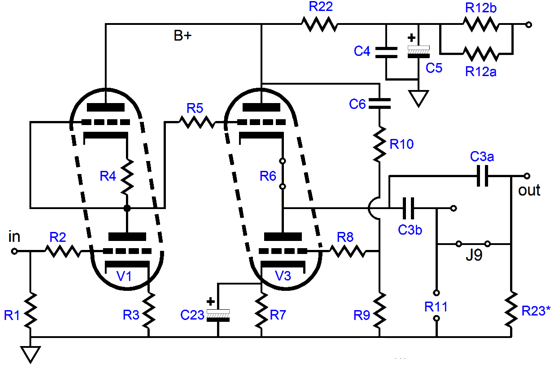
Your Aikido already has an output cap which is "charged" at power on. While doing this there is a ramp up/surge DC at the outputs combined with th high GND reference resistors of 1 MOhm. This surge DC voltage at power on will still happen when you put in an extra superfluous input cap in each input channel of the chip amp. The chipamps input caps will also let the surge DC through as caps like changing voltages and they open the door for them, this is one of their functions...Just remember that caps don't let DC through but rapid changing DC voltages are a bit like eh...AC...
What you do need is a mute circuit at power on which also acts when the pre amp is powered off by shorting the outputs. Please don't use a circuit that puts contacts of the relay in series with the output as now the quality of your precious signal will depend on the quality of the contacts of the relay.
You better use a 100 Ohm resistor after C3a and then the shorting relays contacts, so currents will be acceptable. Maybe an experienced tube tech can elaborate if the tubes won't be affected by this as I don't know that with the specific schematic of the Aikido. All I know is that shorting outputs with solid state stuff clearly gives less plops than switching the contacts in series with the output. When in doubt you can use series switching.
Any circuit with high power supply voltages and output caps should have a mute relay as it will cost money and time to repair the speakers. Better avoid that")
This schematic works very good. They used the contacts of the relay in series with the output and the circuit uses the heater windings for power supply:
Your Aikido already has an output cap which is "charged" at power on. While doing this there is a ramp up/surge DC at the outputs combined with th high GND reference resistors of 1 MOhm. This surge DC voltage at power on will still happen when you put in an extra superfluous input cap in each input channel of the chip amp. The chipamps input caps will also let the surge DC through as caps like changing voltages and they open the door for them, this is one of their functions...Just remember that caps don't let DC through but rapid changing DC voltages are a bit like eh...AC...
What you do need is a mute circuit at power on which also acts when the pre amp is powered off by shorting the outputs. Please don't use a circuit that puts contacts of the relay in series with the output as now the quality of your precious signal will depend on the quality of the contacts of the relay.
You better use a 100 Ohm resistor after C3a and then the shorting relays contacts, so currents will be acceptable. Maybe an experienced tube tech can elaborate if the tubes won't be affected by this as I don't know that with the specific schematic of the Aikido. All I know is that shorting outputs with solid state stuff clearly gives less plops than switching the contacts in series with the output. When in doubt you can use series switching.
Any circuit with high power supply voltages and output caps should have a mute relay as it will cost money and time to repair the speakers. Better avoid that
This schematic works very good. They used the contacts of the relay in series with the output and the circuit uses the heater windings for power supply:
Attachments
Last edited:
OK, thanks for the lesson and thanks for the circuit but I would probably buy something like this, it saves me trouble:
Mute Circuit
Anyway, I need to ponder a few things: like forgetting about tube preamps with transistor amps, for example. It is beginning to be too much trouble. Is it worth messing with my precious signal? Hmmmmmm.....
Mute Circuit
Anyway, I need to ponder a few things: like forgetting about tube preamps with transistor amps, for example. It is beginning to be too much trouble. Is it worth messing with my precious signal? Hmmmmmm.....
Not a lesson but using available knowledge to answer your questions why stuff breaks while going in the wrong direction solving the problem. Sometimes thinking a bit longer does save time later on... You could have saved the money from the destroyed speakers and have the best mute circuit in the world
Eh the device you will be buying does exactly the same but it will save the time for making a PCB. Please aks a tube guru if the tube does not have a problem when the output is shorted. Current will flow to GND when output is shorted via 100 Ohm but that still can be too much with high voltages. Higher value resistors are not recommended as preamps better have low impedance outputs. I guess it's not a problem for the tubes but since I don't know for sure you better ask someone who does know the Aikido well.
Why would you forget using tube preamps with SS power amps ? Your setup is flawed, that is the cause. The preamp lacks a mandatory mute circuit. It also lacks output series resistors which are good practice. Make things simple but not too simple ...
When things are thought over in the design phase such problems would not have occurred. Any quality preamp uses a mute circuit to avoid plops at power on/off. Those that don't have it are excellent speaker destroyers but you know that by now. I can tell hybrid amps have that very same capability so be prepared if you go that direction.
BTW the guys at the website you linked to like to use the muting circuit on their own preamps (when connected to SS power amps) too:
http://www.transcendentsound.com/Transcendent/Transcendent_Sound_Grounded_Grid_Preamp.html
Last edited:
Yes, I know it does the same, the only difference is that I don't have to build it.
Accidents happen and I'm OK with that. This is DIY, some smoke is permissible, once in a while. Yes, if you think about any bad thing that can happen you will take measures like not leaving the house, for example.
When I said I need to ponder things...I really meant I need to listen to things... do I REALLY like the sound of this setup? Is this here to stay? Need more time.
Many times, the pop or thump on the output is linked the capacity of the interstage and filter capacitor values. The larger these are, the longer it take for them to charge to do their job and block the direct current present on the plate or cathode outputs, which ever you are using in your own preamplifier. The net result is a transient or steadily falling direct current presented on the outputs which is certain to wake you up, especially with sensitive inputs like those found on solid state amplifiers. The most sensible way to help reduce this transient or any startup oscillation, whichever may be your case, is to review your capacitor values and reduce them as much as possible without adversely affecting the low frequency response, nor increasing the associated phase shift. I can assure you that you don't need a -3dB point of 5Hz. From here, a mute circuit with a 60 second delay to closed circuit can greatly improve the safety and longevity of your speakers. I also use a delay on the B+ to allow the heater to warm up before the tube begins conducting. Happy listening.
I recently hooked my aikidi pre up to a powerful amp, and notice something similar.. when I get a spike on my mains (heater turning on somewhere in the house, etc), the output of the aikido gets a large slowly alternating voltage that moves my speaker cones all the way in and out.
That's common with some zener regulators and marginal capacitance multiplier designs. I don't know if that's the case in your Aikido, but if you start a new thread and post a schematic of the power supply section, I'll be happy to take a look.
As far as the original question: All amplifiers will have to stabilize to their DC operating points. For tube circuits, this stabilization takes a while. A tube rectified power supply or a regulated supply with slow-start can help, but usually it doesn't remove the problem. The best solution is to wait until the preamp has stabilized (so, say, a minute) before turning on the power amp. The second best solution would be a mute circuit.
~Tom
The best solution is to wait until the preamp has stabilized (so, say, a minute) before turning on the power amp. The second best solution would be a mute circuit.
~Tom
Just wait till you burnt a set of good speakers. You will change the second best solution to first
Never leave possible failure caused by simple human errors to the human brain. One late night, you are awake early the next morning and you just flip the switches for some music and then you smell other smells than the coffee you are making...Other than that you probably are not living alone and your partner one day forgets to use the right "switching sequence"... And then a big quarrel how you can build such stupid audio and then blame her for destroying it...why would anyone like to have a specific "switching sequence" at all ?
Really, when expensive and time robbing failure can occur better invest in the few $ the relay costs (with no negative impact on sound quality at all). You and others in the family can switch whatever you/they want and no speaker will die.
Last edited:
Exactly, the mute circuit should be mandatory. You mentioned a great point, as we are not the only ones to use our own stereo. Perhaps if there is not already one lurking around, we need a delayed relay engage circuit build thread, for both preamps and amplifier outputs. It would be a good sticky thread. I know that I can come up with a few of my own that also sense any direct current offset on the output.
That would not be a difficult board. I was thinking of this for a longer time and thought of the following:
- 1 board with rectifier and filter cap and also DC input supply possibility.
- either power relay or signal relays possible
- 10 or 16 A silver contacts power relays for speaker use
- gold plated silver contact relays for signal muting use
- for preamps contacts in series/shorting to GND possibility
- for preamps 0 Ohm/100 Ohm shorting to GND possibility
- 1 relay per channel with both bifurcated contacts in parallel
- DC detection for speaker protection
- LED indication flashing while muted/glowing steady while unmuted
- both functions on 1 PCB that can be scored (broken in 2 pieces) ?
- 1 PCB with all function integrated ?
Good old uPC1237HA comes to mind for speakers...but I could not find it adequate for use with class D amps with floating outputs...Since I like the device to be multipurpose the project was not finished.
On the other hand a mute circuit for pre amps can be done with very small relays and using just one micro relay on 1 small PCB would probably be a wiser idea for use in solid state gear where space can be tight. Only time delay and fast turnoff at power down is all we need on preamps IMO.
Last edited:
- Status
- This old topic is closed. If you want to reopen this topic, contact a moderator using the "Report Post" button.
- Home
- Amplifiers
- Tubes / Valves
- Tube preamp huge DC thump!