Thanks, audiowize. I don't have any 12-pin tubes but will contact you if I'm interested in buying the UBT-3s.
I got the circuit breadboarded with 6SN7s and managed to do a voltage and listening test. Sound only comes out of the right channel, but what's there is good. The voltages are off between the channels, so I'm guessing there's a bad connection or short to ground somewhere. Haven't been able to locate it yet, so I might have to rebuild the left channel from scratch.
If I switch the tubes, the outage stays in the left channel, so it's not that. All resistors measure to spec.
Here's what I get. Suggestions welcome.
Left
B+1 -- 353
B+2 -- 320
6SN7
P1 -- 138
K1 -- 5.5
P2 -- 104
K2 -- 8
300B
P -- 342
K -- 44
Right
B+1 -- 353
B+2 -- 329
6SN7
P1 -- 146
K1 -- 5.5
P2 -- 185
K2 -- 5.4
300B
P -- 346
K - 38.5
Your voltage measurements are very odd, e.g., Left: P = 342 and K = 44 means, Vpk = 298V, Ip = 44/750 = 58.67mA, how is that possible unless the tube is bad?! Also if Pdiss = 298 x 0.05867 = 17.48W, then it's no where near the max Pdiss of 36W for the 300B. Soemthing is not right...
Your voltage measurements are very odd, e.g., Left: P = 342 and K = 44 means, Vpk = 298V, Ip = 44/750 = 58.67mA, how is that possible unless the tube is bad?! Also if Pdiss = 298 x 0.05867 = 17.48W, then it's no where near the max Pdiss of 36W for the 300B. Soemthing is not right...
I believe the operating point is meant to be around 300Vak/60mA. That's more like 2A3 op points, but given the values of the PT and rectifiers he used, that is most likely it.
I traced the issue to a lead that had come off the plate 2 socket pin in the left channel, so I resoldered it and there's (rather good) audio from both channels.
The voltages around the 6SN7s have evened up pretty well except for around the left 300B. I tried swapping the 6SN7s and then the 300Bs, and the issue remains in the left channel. Here's what I'm getting now:
300B Left
Vp -- 349
Vk -- 56
Vg -- fluctuating positive DC voltage
300B Right
Vp -- 346
Vk -- 39
Vg -- stable -25VDC
I also swapped in different coupling caps incase one of those had gone south, but they test fine when out of the amp and the same thing happens with the new ones.
Must either be a problem with the wiring of the left 6SN7 or 300B, or else one of the components in that chain has gone south, possibly the little 0.047uF coupling cap between the 6SN7 triodes.
It sounds fine -- more than fine actually -- but I don't want positive voltage on that 300B grid.
OK, problem seems to have been a slightly loose connection at the left 6SN7 plate 1 resistor. I tightened that and re-did the entire circuit on the breadboard. Now the results are much closer to what was expected.
The right channel 6SN7 plate 1 is 5 volts higher and plate 2 is 7 volts higher than their left channel counterparts. Everything else is much closer though.
300Bs are now running at 310Vak/65mA, so a slightly larger dropping resistor after the rectifier tube, up from the 33ohm one currently in place, should bring it down to the target 300Vak/60mA.
Left
Rout -- 372
B+1 -- 370
B+2 -- 344
6SN7
P1 -- 148
K1 -- 6
P2 -- 186
K2 -- 5.8
300B
P -- 359
K -- 49
G -- -13
Right
Rout -- 372
B+1 -- 370
B+2 -- 344
6SN7
P1 -- 153
K1 -- 5.8
P2 -- 193
K2 -- 5.7
300B
P -- 359
K -- 49
G -- -13
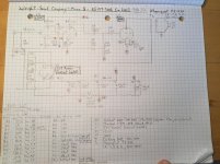
Sorry, forgot about our detour through WPA 3.5 Land. I'm currently listening to the schemo in post #35 (Wright Mono 8 Schematic & Operating Points), the Mono 8 but with 6SN7s, R11 has a 470uF bypass cap, and R13 is 75K.
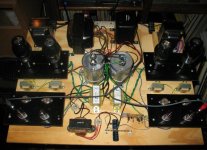
Also because of the breadboard's physical limitations, I've done a stereo build with a 5U4GB rectifier and a split rail power supply, duplicating all of the ground path connections in the original Mono 8.
PT is a Weber with a 660VCT high voltage winding. OPTs are Electra-Print 5K:8ohm, 100mA, 15W.
It's in my main system now and sounds really nice. Good detail and timbre. I'd guess that it's putting out 4-5W and has plenty of power and gain to drive my 91db 2-way monitors in a 14' x 27' living room.
I really need to get an oscilloscope to see what's going on inside.
Attachments
Last edited:
Well if there is a negative grid voltage of -13V, then it could not be based on the schematic in post #35, since there is no connection for the back-bias. To make sure, you can check to see of there is a connection from R13 to the choke.Sorry, forgot about our detour through WPA 3.5 Land. I'm currently listening to the schemo in post #35 (Wright Mono 8 Schematic & Operating Points), the Mono 8 but with 6SN7s, R11 has a 470uF bypass cap, and R13 is 75K.
Well if there is a negative grid voltage of -13V, then it could not be based on the schematic in post #35, since there is no connection for the back-bias. To make sure, you can check to see of there is a connection from R13 to the choke.
Yes, R13 goes to the choke. I didn't draw that connection in order to keep things basic, like PRR suggested. I was thinking about it, though, and in order to avoid the messy awkwardness of all those connection lines back to the PS ground rail and the 300B cathode resistor, I could draw arrows with letter designations as is done sometimes for the PT filament windings and their respective tubes.
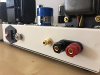
Looking over all of the images I have, the Mono 8's use two-prong power chords, like in vintage equipment, and do not seem to have a ground point per se. I've not even been able to locate a chassis ground point, though it might be there but not visible in the images I have. The HV center tap is connected to the power supply negative rail, which is also connected to the ground tab on the RCA signal input socket.
Do you think it's OK to run it this way, or should I add a chassis ground point for safety? Not sure if it would induce a ground loop buzz or change the operating perameters of the circuit.
Would the neutral connection act as power ground?
Signal ground would exit through the interconnect shield and go to ground via my line preamp, which is properly grounded with a three-conductor power cord and star point.
Last edited:
Would the neutral connection act as power ground?
No, that's very dangerous.
Thanks. I ended up adding a ground point near the third conductor lug, so it's a ground bus configuration. If the ground channel down the power cord creates a ground loop hum, I can just put a two-prong adapter on the end. That way it would still have chassis grounding, and it would all go out the interconnect to the linestage, and to the wall from there.
I had breadboarded this amp in a stereo build, using a 5U4GB rectifier and 6SN7 input tubes, but with the resistor values for the 6EM7 build I had pictures from.
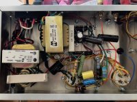
Now I've assembled one of two mono blocks for a final build with all the proper tubes (5Y3GT, 6SN7, 300B), with changes in those resistors to reflect what's in the 6SN7 version that I have pictures for (basically Rk1 goes from 3.1K to 3.9K and R15 from 27K to 75K). I am also using the Magnequest TFA-204 output transformer, which has a max DC current of 60mA.
Initially the voltages were a little north of where they needed to be to keep the 300B Rk below 45V/60mA. Eventually I added a 390 ohm resistor after the 5Y3 to bring everything down. 300B Vk is now at 42.2V and about 56mA.
I will try to get the other one built by tomorrow so I can conduct a listening test. This is basically a 2A3 amp with a 300B stuck in it.
I had breadboarded this amp in a stereo build, using a 5U4GB rectifier and 6SN7 input tubes, but with the resistor values for the 6EM7 build I had pictures from.
Now I've assembled one of two mono blocks for a final build with all the proper tubes (5Y3GT, 6SN7, 300B), with changes in those resistors to reflect what's in the 6SN7 version that I have pictures for (basically Rk1 goes from 3.1K to 3.9K and R15 from 27K to 75K). I am also using the Magnequest TFA-204 output transformer, which has a max DC current of 60mA.
Initially the voltages were a little north of where they needed to be to keep the 300B Rk below 45V/60mA. Eventually I added a 390 ohm resistor after the 5Y3 to bring everything down. 300B Vk is now at 42.2V and about 56mA.
I will try to get the other one built by tomorrow so I can conduct a listening test. This is basically a 2A3 amp with a 300B stuck in it.
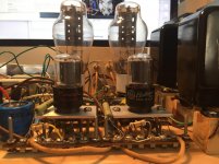
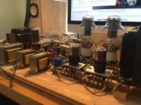
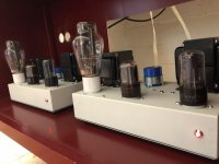
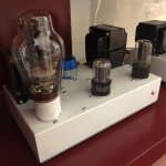
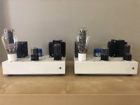
Here are some pics of the build. It sounds really lovely. Much better than I thought it would at such low voltages.
This has been a labor of love for the past couple years. The first tube amps I ever heard, in 2001, were a pair of Wright Mono 8's, customized by George for my friend, using the Magnequest/Peerless TFA-204 output transformers (instead of the stock FS-030). Those amps changed my life, so I've been on a search for lost time to regain that sound. I've breadboarded a number of circuits along the way, and am *very* please with this one.
I'll keep fiddling with the operating points to try and voice it with a higher 2nd order harmonics profile for that "euphonic" sound. I'd appreciate any tips on how to do that.
Thanks for looking/participating.
Attachments

Not sure how well a phone video will sound, mais voilà:
Reverse-engineered Wright Mono 8 with Magnequest TFA-204 OPTs on Vimeo
This one was taken from down in the image:
Reverse-engineered Wright Mono 8 v.2 on Vimeo
Reverse-engineered Wright Mono 8 with Magnequest TFA-204 OPTs on Vimeo
This one was taken from down in the image:
Reverse-engineered Wright Mono 8 v.2 on Vimeo
The trail here may be hopelessly cold, but I'll take a shot just in case... @jdrouin, I read this thread with interest as I have a pair of late production (~2004-5) Wright Mono 8s. I was curious why my amps seemed to have an additional Hammond (5v) transformer in each chassis, which didn't appear in any of the schematics. Then I notice the very same Hammond part shows up in the photos of your final build. Can you help me understand? Would you be interested in seeing photos of my unmodified amps? Thanks! (in case you see this and reply.)
- Status
- This old topic is closed. If you want to reopen this topic, contact a moderator using the "Report Post" button.
- Home
- Amplifiers
- Tubes / Valves
- Wright Mono 8 Schematic & Operating Points