'46 Rock'ola project, as seen here:
http://www.diyaudio.com/forums/tubes-valves/303711-parallel-resistor-tone-control-question.html
and in my other posts.
New issue. When I connect either the ground clip OR the probe tip of a 10x scope probe to the grid of a preamp tube, the heater relay collapses. I checked with a voltmeter and current measurement - B+ drops and current soars. There is also some noise and hum on the output terminals of this tube amp. What is going on?
Is the amp grounded ?
Is the scope grounded ?
If so then you have a scope ground lead that shorts out to ground whatever it is attached to... which is one of the standard hazards of you need to be aware of.
If touching the probe tip does the same... well... you have another issue in addition to the above. First check would be a simple resistive one across the tip and ground lead to confirm there isn't a short.
Is this a 'real' scope or a simple USB do-dah ?
A 10Meg Voltmeter with only (1) lead touching the grid does the same thing. It looks like the apparent difference between the scope probe and the multimeter probe is that the amplifier current drops when the multimeter probe is touching. How does an antenna on the input cause the filament current to stop?
Based on what you now say, the only thing I can think of is that the circuit is totally unstable in some way. Touching a grid could well cause a stage to 'take off' and oscillate but without seeing it all I have no idea why that would kill the heaters. The heater circuit should normally be independent of whatever the rest of the circuit may do.
One possible answer could be that the current rises so high (oscillating) that it effectively loads the transformer so much that the voltages collapse and the relay drops out. That's plausible.
One possible answer could be that the current rises so high (oscillating) that it effectively loads the transformer so much that the voltages collapse and the relay drops out. That's plausible.
that schema is stupid, relay between cathodes and gnd.
even if you put loud music, relay could activate..
why it is there... and dc relay can buzz with ac (music)
Oh yes. That is really weird isn't it. Some sort of protection against overdrive maybe ?
Hpeter, scope is grounded, but amp is isolated in the test described (first test). I just tested a second time, with the amp chassis grounded to the scope. Here are the results:
-DMM lead does not cause heater collapse when 2nd lead is connected to chassis GND (collapse only occurs when a single lead is touching)
-GND clip of probe has no effect on grid during second test (I need to retest)
-Probe of Scope still affects grid 100% of the time (I'll explain what happens below)
-B+ ripple is <.2mVpp for everything except plates of 6L6. ~15mVpp ripple on first cap after tube rectifier.
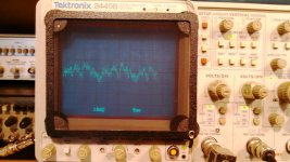
-Here's the Best Part (?!) Ripple/Hum on output terminals is 180Hz + noise. Isn't that 3rd harmonic for 60Hz USA supply? How does that happen? Attached is a photo of the scope screen to show 12 waves appearing across 50mS time span (60Hz usually displays 3 waveforms across 50mS)
Whenever collapse of heater relay coil occurs, a very large ~20 Volt pp signal is produced, with nearly vertical rising edge. It is a transient peak and is not maintained.
-DMM lead does not cause heater collapse when 2nd lead is connected to chassis GND (collapse only occurs when a single lead is touching)
-GND clip of probe has no effect on grid during second test (I need to retest)
-Probe of Scope still affects grid 100% of the time (I'll explain what happens below)
-B+ ripple is <.2mVpp for everything except plates of 6L6. ~15mVpp ripple on first cap after tube rectifier.
-Here's the Best Part (?!) Ripple/Hum on output terminals is 180Hz + noise. Isn't that 3rd harmonic for 60Hz USA supply? How does that happen? Attached is a photo of the scope screen to show 12 waves appearing across 50mS time span (60Hz usually displays 3 waveforms across 50mS)
Whenever collapse of heater relay coil occurs, a very large ~20 Volt pp signal is produced, with nearly vertical rising edge. It is a transient peak and is not maintained.
The amp was stable all week, over an hour of testing with music. The schematic that is shown in the link I provided to a previous post about this amp is not what we have now. The real schematic, as of this past week, routes like this:
Input>6J5 (stock 220v on plate, 2500 on cathode, stock GLoad, all junk removed including bad ITF, tone controls etc. Now, the stock plate resistor and coupling cap are what remains) > James Bax Tonestack >
Now, an ax7/au7 preamp card has been built and added to replace the IT. In the posts above that mention a "grid" being probed, we are talking about the input of this preamp card.
Last night, the new problem started. I swapped out the 6J5 for a 6SN7 (with the intention of adding an extra gain stage, as I still require more voltage gain), rewired all the tube socket pins and started her up. I had problems from the beginning, so I removed the 6SN7 to see if the rest of the circuit was still good. The only soldering I did was on a part of the circuit that has not been connected during testing. However, I am still looking for that "dumb little thing" that escapes the eye sometimes after a project mod, like an improper connection or disconnected lead.
Maybe now i understood this craziness with relay.
Look how fieldcoild is wired, at low volume - relay gives 10~ to heaters to increase tubes consumption (Ig2) also the current thru FC.
At high volumes relay turns on to 6~ ; (G2 consumption is high because of loud music).
Funny way of keeping constant I thru FC. This comes from era when tubes were plenty and cheap, short life was ok.
If you don´t have FC speaker... rather build something else.
One of the other members on here described the heater relay coil differently. By starting out at 10v, the filaments heat up faster, becoming more conducive to the flow of current in less time. When the current in the filaments reaches the amount required to activate the relay coil, the coil is pulled off of the 10v tap and onto the 6v tap for the rest of the duration. I've noticed that the coil switches to 6v somewhere around 8-10 seconds after turn on.
Does anyone have an idea about the 3rd harmonic at the output? There are 2nd harmonic spikes that are vertical transients on the scope, and they (the 2nd's) increase and decrease in voltage with the placement of the scope probe, while the probe is in the air and over the power amp section. Interesting stuff!
The output problems seem to be fed from a dirty B+ at the first filter cap, and just after the rectifier. 10's of volts of a sawtooth waveform. With the addition of my preamp card, the extra current is only 15mA. Total preamp draw is 89mA, with about 60mA going to a 15W 5k load resistor that does nothing for amp, but does load the screens significantly. I mention the currents, because this has become a power supply issue.
- Status
- This old topic is closed. If you want to reopen this topic, contact a moderator using the "Report Post" button.
- Home
- Amplifiers
- Tubes / Valves
- Live Amp Testing: Short created with scope lead?