It would help to see the circuit arrangement. The rating depends on the voltage across the pot as well as the pot resistance. For example 50 volts across a 22k preset would dissipate (50*50)/22000 which is 0.11 watts and so a 0.25 watt part would be advisable.
Resistors (preset and fixed) also have maximum voltage values that should be adhered to. Check the data sheet for confirmation.
Resistors (preset and fixed) also have maximum voltage values that should be adhered to. Check the data sheet for confirmation.
Sorry, but modulating the screen grid of a KT–88 just seems so wrong! And using the “ultralinear tap” of an output transformer running at what +525 V … those control grids are going to be near +500 V. Isn't there a substantial hypercritical issue with the poor things fissioning from over-current draw?
I mean … nominally, as I understand it, the screen grid was once called the accelerator grid, “dignifying” its remarkable purpose that spirited the original tetrode design (from whence pentodes evolved). A gossamer high voltage field generator that'd accelerate electrons toward it, but being gossamer, also thru it. On to the plate! Moreover, when screen grid is held at high voltage (independent of plate), then the plate is free to wobble around in voltage, following amplified signal on control grid. Much good comes from this. The suppressor grid (which in KT–88 is attached to cathode) further insulates the fluctuating plate from the rest of the electron stream, while also nominally slowing down electrons to a drift current instead of a hot current. Also nominally, solves the quickly noted “elbow response” of early tetrodes. Linearizing the tube substantially.
Anyway, I'm probably too long of tooth to appreciate the apparent “upside down” design. I'm old. Just saying.
GoatGuy
He might have changed the grids in the diagram, but the PIN NUMBERS are equally changed. Recipe for disaster.
I wonder if a capacitor bypassed constant current bias source wouldn't be better. (we certainly don't WANT "constant current", but thats what bypass caps are for. Better than first-approximation fixed or second approximation rheostatic pots are for…)
And because P-MOS fets make such good (trivially!) constant current sources…
GoatGuy
Perhaps you “missed the point?”, Osvaldeo de Banfield…
Envision for a moment, the RC or “cathode resistor bias” idea. With no IC, there's no voltage drop. Grid is therefore at cathode (ground) potential. It conducts. Conduction passes current thru RC; E = IR so there's an E that develops. As it does so, the grid, held at ground becomes “relatively negative” compared to the rising VC. Thus there is an “auto-biasing” set up to pull grid negative relative to cathode. At some point a balance is made.
NOT A NEW THING, THERE. Nothing new. We all know this.
But what then is the RC? It is the value that generates a certain voltage when the design-point current flows thru the cathode (and anode). If you want 3 ma, and the tube's transconductance chart shows that at a negative grid bias of –1.5 volts, then you choose ( RC = 1.5 ÷ 0.003 ≡ 500 Ω )
I.e. you choose the resister to correspond to the manufacturer's spec on the valve.
Now… move forward into “constant current” devices. Especially MOSFETs with gate connected to ground, and source passing thru a resistor. (essentially the same as a cathode-bias triode, except MOSFETS are much lower voltage, and perform like pentodes).
What happens? Exactly the same as the above cathode-bias tube. No current, gate is at ground, relative to source, since no current passing thru Rsense. Current develops, and gate goes relatively negative compared to source. This quenches conduction. At some point a “balance point” is achieved, and there's the "constant current".
However, we don't want “constant” current, but a “setpoint current”, which is allowed to vary wildly due to being an OUPUT section. Do we agree? Well, how to bypass the auto adjusting resistance of the MOSFET? Exactly the same as if you used a precisely adjusted potentiometer instead. Capacitor-bypass across the constant-current / auto-adjust-'resistor' section. No difference.
The capacitor would simply pass the A/C signal (current) around the constant current device, as if it weren't there at all. Everyone's satisfied. Nominal no-source quiescent current. Self adjusting precisely due to ageing of tube, dissimilar tubes, and all that. No potentiometer with all its future scratchiness and/or failure modes.
The downside? Oh, that the VA high voltage needs be Vbias higher than otherwise specified, to allow for the cathode voltage drop. Or, one can run the tube “less hot” with voltage, but driven to a different part of its IE power spec.
_______
Now, as an aside, there are WAY more sophisticated circuits that can do the same thing with the concept of a “negative VBIAS rail”. Very small "sense" cathode resistances (on the order of 1 Ω), OP-AMPS to amplify the sense resistance voltage to something "reverse sign" (negative, toward VBIAS), and gently “keep it there” without introducing noise. Heck, its not even that sophisticated. Just use the (-) pin on the op-amp and do a “negative gain” amp section. It works.
Again, both the RSENSE in the cathode string needs fat capacitor bypass. AND the internals of the op-amp also need long time constant filtering. Its another 'adjust-and-forget' technology that works pretty darn well.
Best of luck.
If you still disagree, perhaps read this again.
It holds water.
GoatGuy
> He might have changed the grids in the diagram, but the PIN NUMBERS are equally changed. Recipe for disaster.
Pin numbers in the diagram are correct.
You have turned a drawing error into a major and unnecessary detour through bias techniques NOT shown on this plan.
What pot should Mission720 get??
It's not a tough question. Power rating is rarely critical. RELIABILITY is critical (here a wiper-failure is a major melt-down). Size, shape, and shipping/tax (at London) issues are important.
I have not had to rig such a thing in years so am out of touch with the market. But somebody should know what Mission720 needs.
Attachments
Last edited:
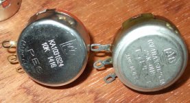
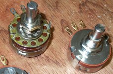
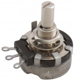
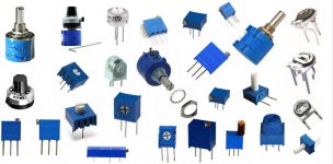
After all the off topic and long winded replies that don't answer your question, I will tell you my recommendations based on many years of building. I always use 2 watt Allen Bradley, Ohmite or Clarostat brand pots as pictured below. (first 4) These controls are sealed from dust and remain trouble free for many years. If used correctly, and not abused, they will virtually outlast you. These come in carbon wiper style and in wire wound configuration. Either type work just as well. Do not use most of the chinchy little ¼W types in the right most picture. I also personally do not like multi-turn controls for bias adjustment because they take too much twisting and I have had reliability issues with some of them. And you simply don't need the resolution they provide. Of course some others will probably disagree.What pot should Mission720 get??
It's not a tough question. Power rating is rarely critical. RELIABILITY is critical (here a wiper-failure is a major melt-down). Size, shape, and shipping/tax (at London) issues are important.
Because I have hundreds of these controls in my personal stock I have not purchased any in a long time. But I'm sure there are equivalent types available today.
Attachments

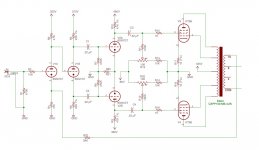
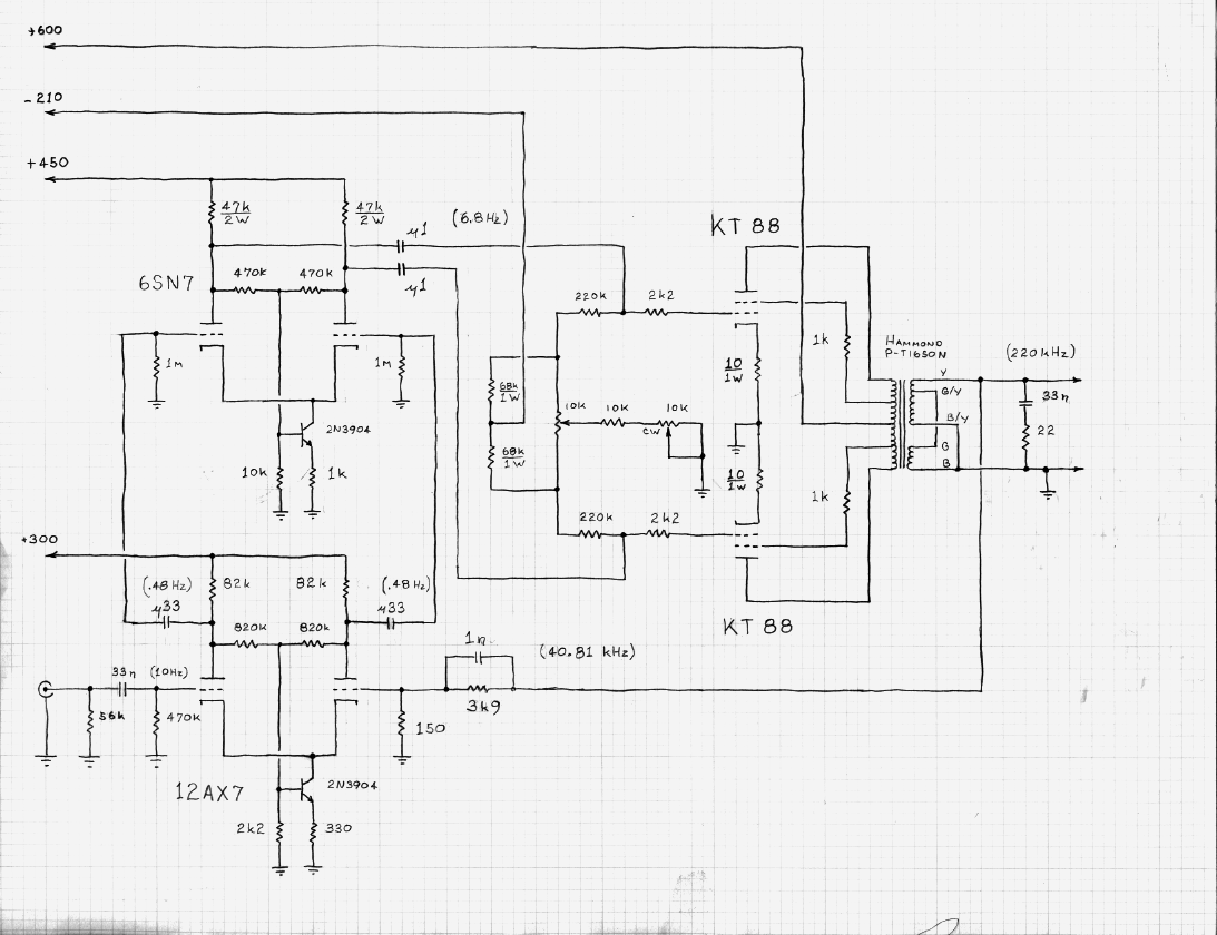
Guys - sorry, I should have pointed out that in the original post where I got the circuit diagram from the poster subsequently stated that the KT88 symbol was incorrect, i.e. showing which was G1 and G2 but the pin numbers were correct.
Not wishing to cause major upsets with the overall design... Of course there will be tweaks and other ways of doing things - I quite liked the simplicity of the circuit and the original poster said the build was rock solid with great performance.
Not withstanding the original circuit, I will be incorporating a few minor tweaks which I have gleaned as beneficial from various articles - notably a 1k resistor from the cathode of V1b to R6 / C2. Can't find the original reference to quote at the moment... so I am prepared to be shot-down-in-flames if that 1k resistor should be elsewehere....
On the point of wiper failure in the trim pots, is there any merit in including a fixed large-ish resistor from the wiper contact to one end of the pot to mitigate against this? If so, which end....
Point noted about a by-pass capacitor from the pot wiper to ground - anyone care to put a value and rating on that? I purchased a bunch of polypropylene 0.1 and 0.22uF caps for the rest of the circuit...
I've posted other queries about this system under different headings to separate the threads so am conscious of repeating here, but my aim is to build an experimental system using inexpensive 6SN7 KT88 (I've picked up some Soviet 'NOS' 6SN7 equivalent a bargain price) which I won't cry about if I blow, then re-build using matched higher quality. Same goes for O/P Transformers.
According to the schem there is 40V across each pot, which is 160mW dissipation. Almost every through-hole pot is rated for at least 250mW. The little blue Bourns trimmers are 500mW. Take your pick, Mission.
http://uk.farnell.com/webapp/wcs/st...72&beginIndex=1&showResults=true&pf=110135389
Don't buy cheap and you won't have reliability issues.
http://uk.farnell.com/webapp/wcs/st...72&beginIndex=1&showResults=true&pf=110135389
Don't buy cheap and you won't have reliability issues.
Yes definitely. e.g. 100k connected from the -80V raw supply to the wiper.On the point of wiper failure in the trim pots, is there any merit in including a fixed large-ish resistor from the wiper contact to one end of the pot to mitigate against this? If so, which end....
Not necessary. Don't overcomplicate. Unless you're in the habit of twiddling the bias while trying to listen to music...Point noted about a by-pass capacitor from the pot wiper to ground - anyone care to put a value and rating on that?
Last edited:
Better use this style of bias circuitry for safety:
http://www.diyaudio.com/forums/atta...1298561958-jj-kt88s-other-octals-kt88_amp.png
regards
Frank
http://www.diyaudio.com/forums/atta...1298561958-jj-kt88s-other-octals-kt88_amp.png
regards
Frank
Ok... I'm not a 'bias twiddler' so am back to my more basic design without the caps. Point noted about a 100k resistor from wiper to negative bias supply... That makes me a little more comfortable with using the 'trimpot' style bias adjust - trimpots all do look a little 'flimsy' compared with robust potentiometer but I guess nearly all are made in China so have to be selective...
The schematics supplied shows a 100k g1 resistor. Thats the limit for KT88 ( and much
to large if one chooses 6550 )
https://frank.pocnet.net/sheets/086/k/KT88.pdf
A smaller value ( 72k ?) would be on the safe side for KT88. If using 6550 50 os the limit.
Why this ? When a tubes has aged somewhat, maybe got a little hot and have gotten some
debris on the grid, then it might get an accelerated bias-run-away that could have been
awoided if a small bias resistor has been chosen.
A lot of amps has this resistor above the documented limit, they get away with it
as long as tubes are fresh, at least most of the time.
The schematics supplied shows a 100k g1 resistor. Thats the limit for KT88 ( and much
to large if one chooses 6550 )
https://frank.pocnet.net/sheets/086/k/KT88.pdf
A smaller value ( 72k ?) would be on the safe side for KT88. If using 6550 50 os the limit.
Why this ? When a tubes has aged somewhat, maybe got a little hot and have gotten some
debris on the grid, then it might get an accelerated bias-run-away that could have been
awoided if a small bias resistor has been chosen.
A lot of amps has this resistor above the documented limit, they get away with it
as long as tubes are fresh, at least most of the time.
Interesting point.
If we sub the KT88 with a KT120, then this resistance should be adjusted as well, let's say a 47K (specs: 51k) ?
Thanks.
If this is a class AB amp then it's probably biased to less than 35W dissipation so the grid leak resistance can be larger than 100k.The schematics supplied shows a 100k g1 resistor. Thats the limit for KT88
g1 resistor... Interestingly I looked at several 'well known' circuit diagrams for KT88 PP and they all have 100k resistor in that circuit position...
The original circuit poster (Loren42) claimed a conservative 50w per channel with solid performance and low distortion.
I am looking for longevity and stability as well as performance so don't want to be operating on the extreme of any characteristic.
The power transformer is deliberately 'generous', the output transformers chosen are rated 100w each. The experimental model will use Edcor OT and for the final I will try SAC silk-wound transformers with the option of C-core.
- Status
- This old topic is closed. If you want to reopen this topic, contact a moderator using the "Report Post" button.
- Home
- Amplifiers
- Tubes / Valves
- Trim-pots for KT88 Bias adjustments