Have a pair of Eimac TL250 and couple of regulated DC power supplies. I'd like to have the tubes tested but unsure how to do it. Help is appreciated.
a) HT power supply - positive lead to the plate. where should the ground lead go?
b) Bias power supply - shall I connect negative lead to the grid ? Where should the ground lead go?
c) Filament power supply - this one is straight forward but I could be wrong, please tell me anyway.
Lastly, I understand a "load" is normally the output transformer....is a "load" required here ?
Thank you
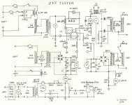
a/ Yes and the ground is the cathode after the load, mentioned later.
b/ Negative adjustable voltage goes to the control grid or grid1 and the ground point.
c/ Filament is centre tapped to ground point.
The load is the measurement of current flowing through the valve dependent on the negative grid voltage and screen grid or grid 2 voltage.
The easiest way to measure the current is to place a 10R 5Watt resistor between the cathode and ground.
Have a look at other valve tester circuits. See here; http://www.popular-hifi.com/projects/nad_stereo/tube_tester_AVO/valvedata20.pdf
and here for a schematic ; http://www.jacmusic.com/Tube-testers/AVO/Mk1/Manual-AVO-Mk1.pdf
Last edited:
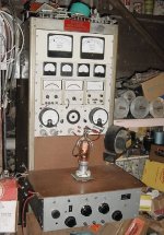
Assuming you mean an Eimac 250TL, filament current is a key factor in testing the quality of a thoriated tungsten filament tube. These types have fairly strict limits on current consumption. For the 250TL it's from 9.7 to 11.2 amps. As the tube ages the filament current rises due to it's chemical composition changing. The test I use for this tube is 2.5KV plate, -120V grid with 100mA plate current. Grid voltage can vary somewhat (10%) to draw 100mA. The acid test is to lower the filament voltage by 10% during test and watch plate current. A strong tube will will not sag, while a weak one will follow downward with the filament loss and act spongy. This is somewhat of a judgment call that requires experience as to how much sag is acceptable. But a true weak tube will be obvious.
Before I built my rack system I had a quick and dirty way to screen out weak tubes from most likely good ones. And this was only for directly heated filament types. I'd make a diode out of a tube by connecting all the elements together. Then, upon lighting the filament, I'd connect it across a 100 volt DC power supply and monitor tube current. A 250TL or TH would draw about 0.45 amps. Then lower the filament by 10% with a variac and watch for current sag (if any) and by how much. This was just a basic DC emission test, but it did follow a more complete class A test although it didn't test for gas or leakage in the tube.
Before I built my rack system I had a quick and dirty way to screen out weak tubes from most likely good ones. And this was only for directly heated filament types. I'd make a diode out of a tube by connecting all the elements together. Then, upon lighting the filament, I'd connect it across a 100 volt DC power supply and monitor tube current. A 250TL or TH would draw about 0.45 amps. Then lower the filament by 10% with a variac and watch for current sag (if any) and by how much. This was just a basic DC emission test, but it did follow a more complete class A test although it didn't test for gas or leakage in the tube.
Attachments
- Status
- This old topic is closed. If you want to reopen this topic, contact a moderator using the "Report Post" button.