Hi, I have a cheap 6sn7 preamp board which is similar to this on ebay.
6Z5P+6N8P*2?6SN7?Tube Pre-amplifier Assembled Board Bile Rectifier for HIFI AMP | eBay
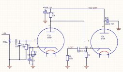
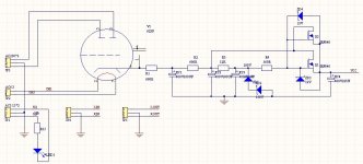
I was wondering is there is any possible tweak to the circuit as shown below.
I am fairly new to the tube scene so tweaking it will be a learning experience.
Also, while the circuit says 250V before the plate resistor, I am only getting around 220v for mine.
I have tried 3 other cheap tube preamp from buffer to a srpp circuit and so far this is the best sounding one using the 6sn7 (Note the tube I am using now is the Pvsane CV181 T2, 6sn7 equivalent)
TIA
6Z5P+6N8P*2?6SN7?Tube Pre-amplifier Assembled Board Bile Rectifier for HIFI AMP | eBay
I was wondering is there is any possible tweak to the circuit as shown below.
I am fairly new to the tube scene so tweaking it will be a learning experience.
Also, while the circuit says 250V before the plate resistor, I am only getting around 220v for mine.
I have tried 3 other cheap tube preamp from buffer to a srpp circuit and so far this is the best sounding one using the 6sn7 (Note the tube I am using now is the Pvsane CV181 T2, 6sn7 equivalent)
TIA
Attachments
I was wondering is there is any possible tweak to the circuit as shown below.
If you don't need all of the gain, remove the bypass capacitor on the input tube's cathode resistor.
This will sound better. What resistance value is the volume control?
Last edited:
If you don't need all of the gain, remove the bypass capacitor on the input tube's cathode resistor.
This will sound better. What resistance value is the volume control?
Funny, I did exactly that. I didn't put in the cathode capacitor because I don't need the extra gain.
I used a step resistor 50k volume. I didn't know the resistance value of the volume would make a difference?
For rectifier, I am using a CBS 6x5gt. I also have a Tung Sol one to try.
I may try a solid state rectifier later to up the voltage. I have the STTH6110TV2 recommended in jeff place. But don't know how to implement that yet.
http://jeffsplace.me/wordpress/?p=7727
Not sure what you want to achieve by tweaking - a dramatic improvement in sound if any is not going to result.
If one must analyse the circuit, what strikes me is a rather high anode voltage for V2A, leaving V3A with a small signal voltage room. What are those voltages? R6 = 1K is rather high for an anode load (R7) of only 15K. (Theory dictates that having an anode load resistor in the vicinity of the Rp - the tube internal resistance - is a condition of higher distortion than with the anode load several times Rp.) Otherwise as Rayma said.
But again for low signal amplitude I rather doubt that any very audible change will result as said.
I didn't know the resistance value of the volume would make a difference?
Only in as much as it will affect h.f. response as a result of Miller effect, depending on its setting. But with a low Rp tube such as the 6SN7 it is unlikely to affect audio frequencies.
Not sure what you want to achieve by tweaking - a dramatic improvement in sound if any is not going to result.
If one must analyse the circuit, what strikes me is a rather high anode voltage for V2A, leaving V3A with a small signal voltage room. What are those voltages? R6 = 1K is rather high for an anode load (R7) of only 15K. (Theory dictates that having an anode load resistor in the vicinity of the Rp - the tube internal resistance - is a condition of higher distortion than with the anode load several times Rp.) Otherwise as Rayma said.
But again for low signal amplitude I rather doubt that any very audible change will result as said.
I got around -4.5V for the grid to cathode for the 1st stage and a very low 0.09V and 0.27V for the 2nd stage. Is this normal for the 2nd tube?
So for the 1st tube, for a plate resistance of 7700R, 2X is a bit low for plate resistor.
I don't expect drastic change in sound quality, just minor change and hope to learn something in the process. But just tube rolling to the Psvane cv181 made a huge improvement.

Last edited by a moderator:
- Status
- This old topic is closed. If you want to reopen this topic, contact a moderator using the "Report Post" button.