Hi all. I have been using and enjoying a CATO line stage for a few years now. A few days ago, while listening to some music, really loud noise came out from speakers. Turned everything off and left it alone for the night. Next day tested it at low volumes and at first is all ok, but after a few minutes I get a big thump in one of the channels. I can see the cone sticking out for a second or two and then back in. A few seconds ok and then the thump again. Did not clock the time between thumps but it is periodic.
Any idea on what may be causing the problem?
Thank you all
Any idea on what may be causing the problem?
Thank you all
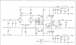
That circuit appears to have borrowed the input LTP from an SS amp, but used triodes instead of BJTs. Unfortunately this circuit is balanced in its BJT form but not in its triode form because BJTs have high collector impedance but triodes have lowish anode impedance. As a result, the current mirror anode load will unbalance the LTP.
We then face the issue that it superficially looks like a balanced input but it is not a balanced input because the feedback will seriously unbalance the input impedances at the two inputs.
Then a simple (and harmless) output coupling cap is replaced by a DC servo - which is possibly the source of the OP's problem.
It looks like it was designed by someone who thinks he understands circuits.
That circuit appears to have borrowed the input LTP from an SS amp, but used triodes instead of BJTs. Unfortunately this circuit is balanced in its BJT form but not in its triode form because BJTs have high collector impedance but triodes have lowish anode impedance. As a result, the current mirror anode load will unbalance the LTP.
We then face the issue that it superficially looks like a balanced input but it is not a balanced input because the feedback will seriously unbalance the input impedances at the two inputs.
Then a simple (and harmless) output coupling cap is replaced by a DC servo - which is possibly the source of the OP's problem.
It looks like it was designed by someone who thinks he understands circuits.
+1
Sorry to be negative so early in the morning (RSA time).
Regarding your problem, difficult to say without checking point to point. D.c. upset in a d.c. feedback circuit can be a bother to find.
Next I would do..
Resolder the pcb.
Specially solder joints with large thermal changes (tube sockets and so on).
They tend to open (bad contact) by time. This might also be difficult to spot, so it's faster to just solder.
Also the P1 potmeter, could be bad.
Note , disconect your poweramp and speaker if you turn it with power on.
- Status
- This old topic is closed. If you want to reopen this topic, contact a moderator using the "Report Post" button.
- Home
- Amplifiers
- Tubes / Valves
- CATO linestage. Periodic DC offset problem.