Simply to hit a voltage with a transformer I could find in my junk bin I built a choke input power supply for the first time. Silicon full wave rectifier (each diode capacitor bypassed), 280 V AC to 250V DC, 50 ma. Big-a55 150ma 10Hy choke (garage sale prize) for the input, then 220 uF cap and a smaller choke to supply the output stage for a 3w SE amp, still kind of slop-built on my bench. So far so good.
After putting it into use the buzz and hum in the amp was very noticeably worse. Dinking around a bit I found that just touching the big choke, or moving tools or my hand around it, hugely affected the hum. Wrapping it with a couple layers of grounded copper foil and sticking a grounded piece of steel sheet between it and the amp minimized the problem, but it's still there
Is this just inevitable with choke input power supplies, or is there a smarter way to put them together? Right now putting the power supply at a distance from the amp is as good an idea as I have.
Last edited:
Hello,
Maybe it has been dropped during his life.
Most chokes dont like choke input because it makes them work harder.
Could be that it is a choke designed for 800 or 400 cps/hertz like the ones used in aeroplanes and these chokes dont like 100 or 120 cps.
I would try to find a choke with lower current rating so you will get more Henry for the same seize. And use a bleeder to take care of minimum current.
greetings, eduard
Have you tried adding 0.47-0.68µF (low inductance MKP -- stacked film construction type), connected right after the rectifier?
A cap of this value can reduce undesirable turn-ON and -OFF effects of the inductance: fast-slewing voltage waveforms, unexpected resonances with parasitic capacitance,etc.
Please try to get within this exact range, or the dc output voltage may increase (C value too high) or the effect worsened (too low, 100n etc)
When you say there is hum, is it mechanical, or is it heard in the amp output (speakers)?
Or is it both?
How did you orient the choke windings versus the output transformer windings.
They should be far apart, and even with that they should be at right angles.
Is your chassis Steel, or Aluminum?
If it is steel it will make mechanical noise, and will also couple the magnetic energy to the output transformer. Single Ended air gapped EI transformers are more susceptible to magnetic coupling than Push Pull EI transformers.
The input choke can magnetically couple to the second choke. There needs to be enough capacitance after the second choke if they are coupled either through steel chassis, or are close and not oriented at right angles.
Yes, you do need to have a proper bleeder resistor, not just for startup rise of B+, but also for safety reasons.
Make sure that the small capacitor before the choke mentioned in post #4 does not resonate with the choke at 2 times the line frequency.
Resonance, fo = 1/(2*pi*(Root of L * C)).
Example 0.5 uF and 10Henry:
fo = 1/(2*3.14*(Root of 10 * 0.5*10-6))
fo = 71 Hz
0.25uf and 10Henry, fo = 100.7Hz. Bad for 50Hz power (2*50 = 100Hz).
Even a little too close for 60 Hz power (120Hz).
Resonance can cause high voltage (higher voltage than what you get with non resonant cap input, and non resonant inductor input supplies).
The choke in a choke input PSU has the full secondary AC voltage across it so it is likely to emit a significant AC magnetic field. The same choke used as a smoother in a cap input PSU might only see 5-10% of the AC voltage, so much less AC field. For the same reason mechanical vibration of the choke will be worse too.
As said by the two previous posters.
The (alternating) magnetic field around a L-C filter is severe, as is the possibility of 'radiation' by particularly live choke lead. (My experience is with use in a 600V 500 mA supply filter.)
I myself had to move the choke around in order to find a position of minimum interference. The core gap should be as far away from other inductive components as possible as suggested above. This gap field can even induce hum in the elements of nearby tubes. Routing of leads play a role, particulaly the 'live' (ex-rectifier) lead, also an advantage if that lead can come from the 'inside' of the choke (end of winding next to the core - but proper insulation is required). I presume you also took care of a suitable R-C network across the choke or at the rectifier side to calm spikes generated when the rectifier turns off. (Reaching an optimum situation here requires the use of an oscilloscope and suitable high voltage probe.)
I finally had to use an eztra transformer steel magnetic shield inside the outer steel enclosure (with the necessary mechanical fixing against movement!) to get the interference as low as when the choke was at a distance.
All a bit daunting for the experimenter; a warning to leave enough room for the necessary maneuvres or work on a prototype first.
Disconnect one end of the cap across each of your diodes, place a 100R - 1000R carbon comp resistor in series and re-connect to the diodes.
You need a snubber/Zobel in parallel with the diode, not a cap.
Changing to UF4007 or similar low noise diodes, not regular silicon diodes like 2N4007.
http://www.vishay.com/docs/88755/uf4001.pdf
You need a snubber/Zobel in parallel with the diode, not a cap.
Changing to UF4007 or similar low noise diodes, not regular silicon diodes like 2N4007.
http://www.vishay.com/docs/88755/uf4001.pdf
I like to use choke input when I can. But as you can see, it does require more care.
It does tend to make the power transformer cooler.
And I agree that it should be series RC snubbers, not the capacitors across the diodes
(although I have never used either in any of my amps).
BTW, it is 1N4007 diodes, not 2N4007 Bi-Polars as the 'typo' above had it.
It does tend to make the power transformer cooler.
And I agree that it should be series RC snubbers, not the capacitors across the diodes
(although I have never used either in any of my amps).
BTW, it is 1N4007 diodes, not 2N4007 Bi-Polars as the 'typo' above had it.
Put in the cap Rod suggested, or do it when you replace the shorted rectifiers - which will happen sooner or later if the cap isn't there. Any choke input with solid-state rectifiers needs an input cap or MOV to protect against transients. .047 MAY be enough, .1 or more is better.

For a full wave power supply, If you put a cap to ground before the choke, and IF it resonates at 2X your power line (120Hz for 60Hz power, or 100Hz for 50Hz power),
then . . . . You WILL almost certainly blow up the solid state diodes at first turn on.
Resonance = 1/(2 * pi * (Root of L * C))
pi 3.14, L in Henrys, and C in Farads
See post # 5 above.
Resonance = higher voltage than the source voltage.
Do the math, you will be able to predict whether it is going to blow up or not.
Make sure that the small capacitor before the choke mentioned in post #4 does not resonate with the choke at 2 times the line frequency.
Resonance, fo = 1/(2*pi*(Root of L * C)).
Example 0.5 uF and 10Henry:
fo = 1/(2*3.14*(Root of 10 * 0.5*10-6))
fo = 71 Hz
0.25uf and 10Henry, fo = 100.7Hz. Bad for 50Hz power (2*50 = 100Hz).
Even a little too close for 60 Hz power (120Hz).
Resonance can cause high voltage (higher voltage than what you get with non resonant cap input, and non resonant inductor input supplies).
A few questions. Is the only resonant frequency to be avoided 2xline frequency, so that in the US I just need to make sure it stays well above or below 120Hz? Is one side (above or below) preferable. Since I'm running the power supply well under the rating of the choke I penciled out some figures for 10, 15 and 20Hy. Looks like below roughly .05uF and above roughly .22uF are unconditionally safe, if I did the math right.
Last edited:
I would stay away from these 2 possible Combinations of L and C that you gave:
20H and 0.05 uF f = 159Hz
10H and 0.22 uF f = 107Hz
Those resonances are too close to 120Hz.
And the tolerance of the choke (+/- %) at the load current, and tolerance (+/-%) of the capacitor could bring you even closer to resonance.
Keep in mind that an input capacitor will raise the DC voltage of the power supply output.
Take a secondary of 700V (350V to center tap). It will present 350V * 1.414 = 495V peak to the full wave solid state rectifiers.
Suppose the DC current on the power supply is 100mA (0.1A).
Capacitive reactance, Xc = 1/(2 * pi * f * C)
Example for 1.0 uF:
Xc = 1/(2 * 3.14 * 120 * (1.0 * 10-6F))
Xc = 1,326 Ohms
0.1A * 1,326 Ohms = 132V peak to peak ripple at the point of the 1uF and 20H choke.
The middle of that ripple is 66V. 500V peak - 66V = 434VDC out of the choke.
Of course it will be less than 434V, since there will be voltage drops due to the DCR of the 1/2 windings of the secondary, and due to the small rectifier drop (much more with a vacuum tube rectifier), and (after the choke) due to the DCR of the choke.
Keep in mind that the drops are not 0.1ADC times the DCR of the secondary 1/2 windings.
That is because the capacitor causes transient currents that are much larger than the DC current.
495V peak/1,326 Ohms may easily have transient currents of up to 0.373A (373mA).
The transient is much shorter than that of a 1/2 alternation of 60Hz. The effective wave shape has frequencies higher than 120Hz, so the transient current may be even larger.
A full wave, true choke input supply has 0.9 times the rms voltage of the 1/2 secondary.
700V CT, 350Vrms to CT.
350V * 0.9 = 315V
Of course, the voltage will be less than that, because of the voltage drop of the secondary 1/2 winding DCRs, the diode drop (or tube rectifier drop), and the choke DCR drop. But the transient currents are Much less than those of a Cap input supply, so the drops are all correspondingly lower.
The choke works on an average current principle.
Xl = 2 * pi * f * L
10H
Xl = 2 * 3.14 * 120 * 10H = 7,540 Ohms.
Power supplies are fascinating in their details.
Last edited:
It needs to be kept in mind that a capacitor (with/without series resistor) does as much of a commutating job here as being capable of causing resonance - every half cycle diodes go back into conduction, thus quenching resonance tendencies. Too small a capacitance might have the danger of exciting h.f. oscillation, which is then of course the wrong value. To repeat: If available an oscilliscope gives a lot of insight into the effect of whatever R-C network is applied over diodes or at the choke input. (Quoting possible R-C values here is of no meaning as values will depend on the particular circuit.)
Not to belabour the resonance aspect, but a parallel L-C network resonant at the ripple frequency has in fact been used to advantage before. It requires a smaller value choke to give a high parallel resonance impedance at the ripple frequency. It is however not popular because the impedance is capacitive at high frequencies, aiding in dumping mains carried noise onto the h.t. harness.
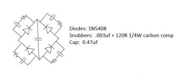
Here's what I ended up with last night. Parts chosen based partly on what I had a lot of on hand. The only thing that required some testing was the value for the cap before the choke. I tried various values and 0.47uF was the largest that didn't cause the voltage to rise. I was surprised at how quickly this rise sets in with larger values. It's already substantial at 1.0uF. This was testing with a 50ma load, one channel of what may someday be a complete amp, so basically half load.
Theory and practice lines up perfectly well here, the PS is now dramatically quieter electrically. In fact I almost can't hear the hum in the speaker anymore, I need to use headphones. Even here the hum is near noise level. Nice, thanks to all...
BTW, the amp is basically wired in the open on top a breadboard, I hope in a proper case the hum may go to almost nothing.
Attachments
geezertron,
It is good that you got the power supply running quietly.
I have had some output transformers that "sing".
I use chokes that are made for choke input. They do not hum mechanically (at least not that you can hear).
I measure amp output hum sometimes as low as 100uV into 8 Ohms.
It is good that you got the power supply running quietly.
I have had some output transformers that "sing".
I use chokes that are made for choke input. They do not hum mechanically (at least not that you can hear).
I measure amp output hum sometimes as low as 100uV into 8 Ohms.
- Status
- This old topic is closed. If you want to reopen this topic, contact a moderator using the "Report Post" button.
- Home
- Amplifiers
- Power Supplies
- choke input PS throws noise like crazy