As Tom alluded in post #11, the use of silicon diodes makes choke input filtering much more problematic. The soft switching of valve diodes made life a lot easier back then.
Chokes don't like the instantaneous glitch in current flow that happens when the diodes commutate. The main aims when using solid state diodes are:
- use a C-RC snubber across the secondary HV winding(s) (aka quasimodo style).
- use fast diodes (eg. UF4007), and don't use diode snubbers.
- use a small cap or MOV from the output of the diodes to the CT-first filter cap negative terminal, to shunt any remaining transient currents from commutation to the most appropriate star point.
- connect the 'inner' end of the choke winding to the diodes (that may help better screen the high dV/dt waveform at the output of the diodes), and ground the choke core.
Last edited:
Thanks for your input. May I ask you for your view on the setting No. 5 at the BOTTOM of this page:
5U4G-Mesh and 5Z3-Mesh Data sheet. Emission Labs.
Direct link:
http://www.emissionlabs.com/datasheets/RECTIFIERS1-small.jpg
Quote:
"Circuit 5: This is how to connect a double coil Choke, such as the Lundahl LL1673 or similar products. Beware the polarity of the connections. (the dots in the circuit diagram here). The importance of this circuit is very high. We have complete inductive separation of the transformer from the amplifier. Definitely, the transformer capacitance from primary to secondary can not inject an AC hum current into the amplifier any more.
Design Quality of Circuit 5: Five Stars ***** "
Actually all my chokes are build like Lundahl's, but so far I did not want to experiment too much and used the normal choke-setup wit hthe choke in the HV, but Rectifier-Output from the the mid-tap of the heater winding (bleeder in place).
I could change this to CMR-setup if this makes stuff quieter. I guess you can not only do this with cap-input, but as well with choke-input ?
Placing a choke in a grounded polarity path may accentuate the parasitic noise path from the HV secondary winding and the chassis ground of the power transformer. This noise effect was noticed back in 1934 (by none other than Terman himself) when chokes were placed in the negative only path (to avoid the insulation requirements for chokes in the positive path).
https://dalmura.com.au/static/Note%20on%20a%20cause%20of%20residual%20hum%20in%20rectifier%20filter%20circuits%201934.pdf
How well a common-mode choke applied to both positive and negative paths would perform probably requires some careful set up and comparative testing of the noise spectrum when only one item is changed - eg. choke in positive leg, choke in negative leg, chokes in positive and negative leg, common mode choke (hopefully with same differential inductance).
Last edited:
I got it completely quiet now by simply exchanging the whole set of tubes (801A)...I will start to test which of them died and made the trouble....but in the end the PSU as well in choke-input was perfectly quiet. Interesting though that the behavior of the dying tube was very sensitive in producing noise when switch from LC to CLC...
Thanks for all the support...my mistake not just to exchange tubes first...after now many hours later I will do this first thing next time...
Thanks for all the support...my mistake not just to exchange tubes first...after now many hours later I will do this first thing next time...
Jeepers Blitz,
My initial thought was that you are lucky - but somehow that term does not appear to be right") What I mean is that I am still struggling as per previous posts.
What I mean is that I am still struggling as per previous posts.
I would venture to say that a sub-normal tube may have taken your minimum current draw for your particular circumstances to a too low value (hope I am not overlooking previous posts). Such a behaviour could have been checked by adding a little extra load just for testing, but it is cumbersome in the sense that one does not always have a suitable high dissipation resistor handy. This worked for me in taking the power supply operating conditions just out of the filter minimum current requirement. (I did not read back; are we still talking about noise over the speaker(s)?)
But happy for your part; perhaps you can favour us here with the result of your tube analyses, i.e. to what degree was any tube(s) below par.
Thanks for that post!
My initial thought was that you are lucky - but somehow that term does not appear to be right
What I mean is that I am still struggling as per previous posts.I would venture to say that a sub-normal tube may have taken your minimum current draw for your particular circumstances to a too low value (hope I am not overlooking previous posts). Such a behaviour could have been checked by adding a little extra load just for testing, but it is cumbersome in the sense that one does not always have a suitable high dissipation resistor handy. This worked for me in taking the power supply operating conditions just out of the filter minimum current requirement. (I did not read back; are we still talking about noise over the speaker(s)?)
But happy for your part; perhaps you can favour us here with the result of your tube analyses, i.e. to what degree was any tube(s) below par.
Thanks for that post!
Disconnect one end of the cap across each of your diodes, place a 100R - 1000R carbon comp resistor in series and re-connect to the diodes.
You need a snubber/Zobel in parallel with the diode, not a cap.
Changing to UF4007 or similar low noise diodes, not regular silicon diodes like 2N4007.
http://www.vishay.com/docs/88755/uf4001.pdf
Why Carbon Comp resistors ?.
Dan.
Here's what I ended up with last night. Parts chosen based partly on what I had a lot of on hand. The only thing that required some testing was the value for the cap before the choke. I tried various values and 0.47uF was the largest that didn't cause the voltage to rise. I was surprised at how quickly this rise sets in with larger values. It's already substantial at 1.0uF. This was testing with a 50ma load, one channel of what may someday be a complete amp, so basically half load.
Theory and practice lines up perfectly well here, the PS is now dramatically quieter electrically. In fact I almost can't hear the hum in the speaker anymore, I need to use headphones. Even here the hum is near noise level. Nice, thanks to all...
BTW, the amp is basically wired in the open on top a breadboard, I hope in a proper case the hum may go to almost nothing.
I have same issue as what you have mentioned. It looks like I have underestimated the rectifier in the case.
I have used one 50Amp bridge block rectifier ( i had them in stock ) with 100nF across each pins of the bridge block and used the following way
LCLCRCRC
a 2H - 220uF - 1.5H - 220uF-56ohm - 1.2kohm
I had that buzzing issue my load is 110k bleeder and tube pre mufollower 6sn7 with bias of about 6ma so technically the load is 6ma and would be using for stereo for 12ma or 16ma for max 2 channel so I had the same strange issue of noise and hum very low level but audible through speakers.
Can the above arrangement of using snubber of 0.03uF with 120ohm resistor across each diode and 100nF across the bridge before the choke solves the problem?
I have thought another way is to use a flyback diode across the choke? how about that one? can we use it? Or any arrangement if anyone could suggest.
As per the page audiofilterchokes-page2
Calculated choke size will be large for a smaller current load like if the calculation is taken into consideration then we need about 60H of choke in the above case.
Im trying to increase the current consumption in bleeder to compensate the choke size to a very decent level like right now for 6ma of current im getting about 60H of choke required hence thought to burn some more power in bleeder resistor like in about 50ma in total burning along with bleeder resistor to test so what I find is at 340V 50ma of consumption we need about 7.5H.
I do have few chokes in stock like 2H , 1H, 1.5H etc so can we stack the chokes in LCLCLCLC configuration to get the total inductance value ?
Or do we need to have 10H right at first choke?
A choke INPUT filter for low current needs a big choke.
This has to be "all one electric lump". Yes, you can series multiple chokes. However it takes many-many 2H chokes to make 60H. (They just sum. If they were added windings on one core it would multiply, but you can't do that with a pre-made choke unless you rewind it with fine-gauge wire.)
Sucking more idle current seems a very silly thing to do. It inevitably makes more raw ripple. Getting the choke current continuous (your first choke is cutting-out every half-wave and throwing hash) will reduce buzz, but maybe not in the same proportion.
For a mere 6mA, I can't think of a thing wrong with R-C filtering. A cap-input to get excess voltage, then waste that off in a string of R-C filters. Throw in a choke for "looks" if you please.
I continued working not only to get the PSU quiet, but as well to listen carefully what sounds best.
Depending on your current and voltage, there is a point IMHO where you get the liquidty and fine tone vibrations especially right, where you get sonically the best of two worlds. Typically it is the point where you have a small C (like 0.5uF-1.5uF) after the rectifier and where your voltage is not or a just a few volts raising. This gives the stiffness/sharpness in focus of the choke-input in combination with the liquidity and musicality of Pi-filter. You get bigger and you have a much more soft sounding, les transaprent amplifier...just try it yourself if you can hear this. All my PSU are now (c)LCLC with chokes being six chamber chokes with amorphous cores from our DIY-colleague 50AE and Caps being CDE 947D Polyprop.
Depending on your current and voltage, there is a point IMHO where you get the liquidty and fine tone vibrations especially right, where you get sonically the best of two worlds. Typically it is the point where you have a small C (like 0.5uF-1.5uF) after the rectifier and where your voltage is not or a just a few volts raising. This gives the stiffness/sharpness in focus of the choke-input in combination with the liquidity and musicality of Pi-filter. You get bigger and you have a much more soft sounding, les transaprent amplifier...just try it yourself if you can hear this. All my PSU are now (c)LCLC with chokes being six chamber chokes with amorphous cores from our DIY-colleague 50AE and Caps being CDE 947D Polyprop.
6-12 mA load? Doesn't it looks like it will be better with RC-filter, not LC? We can even start with R after diode bridge. Because small load really needs a lot of Henrys (I'm silent about active filters ets).
I mean not one RC, but two-three (just change L to R in existant rectifier). It have to be totally not resonant and may be even smaller phisically.
I mean not one RC, but two-three (just change L to R in existant rectifier). It have to be totally not resonant and may be even smaller phisically.
Last edited:
RC-snubber before the bridge (don't know exact, may be 0.1 uF and 120 Ohm is a good point) may be much useful and effective, then four C parallel to bridge diodes. Four parallel C isn't best way to get rid of hum-noise.
Hi Vovk can you please explain that do we need to have a RC network shunt before the bridge? I never saw this alignment.
Secondly 4 x C parallel across each diode in the bridge rectifier? or after the bridge rectifier?
Typically it is the point where you have a small C (like 0.5uF-1.5uF) after the rectifier and where your voltage is not or a just a few volts raising.
Nice tip
May i ask what cap do you use in this position? Something tells me this cap is going to be very audible.
There are several topics here about RC-snubbers, I'm afraid I can't add more. I just can approve that they are really useful.Hi Vovk can you please explain that do we need to have a RC network shunt before the bridge? I never saw this alignment.
Secondly 4 x C parallel across each diode in the bridge rectifier?
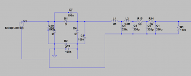
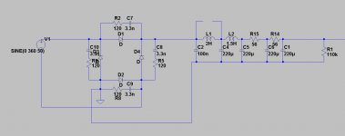
4xC - I'm talking about parallel to four diodes, first schematics (C7-C10).
Snubbers on the second schematics could be good, but it seem to me that they four can be replaced by one.
Last edited:
Finally it seems the hum + noise problem is solved but with extremely low hum residue. The following changes I have done
1. Changed the diode bridge to MUR1560
2. 0.47uf connected across the bridge as suggested in the earlier posts.
3. used cRCRCRC filter instead of choke
47uF | 1.2k | 220uF | 1.2k | 220uF | 1.2k | 220uF
4. Used Hum dinger adjustment
5. Elevated the heater rail voltage to around 65V
6. used small 47uf as the first capacitor after the rectifier instead of 220uF
7. Used a 2.2k resistor at each B+ of the preamp
8. 220uF bypassed with a 2.2uF decoupling capacitor after the 2.2k resistor.
9. used 47ohm as hum breaking resistor in the B+GND before the signal ground.
Now the entire unit is on test bench and on the scope Im getting less than 0.5mv of output hum not noise. I have tried adjusting the hum dinger to compensate it but not its not reducing beyond this point.
There are two possibilities what I think. Either If I go with DC heaters? Secondly since the entire preamp is on test bench instead of chassis Im thinking that little hum would disapper once everything is in chassis? Is it possible?
Since the noise is diapppeared i mean its extremely faint now including the hum cannot hear at 1mtr distance with a 88db speaker. But I have 100db speaker at my home so im worried that the hum would be audible hence want to kill that last residue of hum .
I got few ideas that can we use an inverting amp using single transistor and connect the output to the ground and adjust that last bit of hum? or if that can be solved once in chassis I think that would be great.
All the above inputs given by the members are really helpful. Thanking very much to all of you. But please suggest me few things to remove that 0.5mv of hum on the output.
What I have observed is that initially it looked like saw tooth waveform but after adjusting the hum dinger it looked like a proper sinewave.
Another question that I have is that do we need to use different hum dingers for different pre stages? Like If I want to make 8 channel for mixing application do I need to use 8 channels of hum dinger independently or just one hum dinger is sufficient for all?
- Status
- This old topic is closed. If you want to reopen this topic, contact a moderator using the "Report Post" button.
- Home
- Amplifiers
- Power Supplies
- choke input PS throws noise like crazy