Hello guys,
since there is no schematic on the net, I visually rebuilt the connections, I noticed that the schematic is much like Little Bear Tube preamp.
I want to try to improve it and I want to reduce the gain, what do you advise?
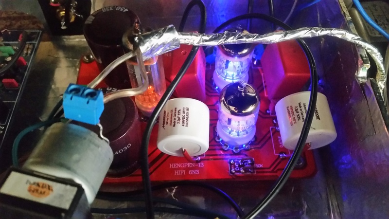
These are the values and schematic detected in my preamp Preamplificatore valvolare stereo
HELLO,
-Work update in progress; So, I deleted the volume potentiometer put out and put in its place du resistance from 47K, I put two input resistance from 470K in place of 10 K. I connected input a pot volume of 100k, replaced the capacitors 4 by 2,2uF (I had them all to a brand, put two and two WIMA Mundorf). The greatest effect obtained, at the time, is the Volume control now a regular and not too aggressive as before, perhaps pot original Linear and poor .... The sound, however, is not like very poorly defined and lacking in detail and recently extended the low Range ..... I accept your advice more
Under Now schematic llo with values....
..... eliminating the output volume pot, and put it in the hall, now the control is correct and not requiring regular reduction in gain, but the sound quality do not really like. My intention is groped to improve the sound quality ...... I already have seen this PCB ...
6N3?
6N3, Tube 6N3; Röhre 6N3 ID21974, Half-Wave Vacuum Rectifier
I suspect you mean 6N3P
https://frank.pocnet.net/sheets/112/6/6N3PE.pdf
If you increase R8 to 1k2 that should reduce the gain. There is a mismatch though, 33k anode load working into a lower than 8k load. (47k load resistor in parallel with 10.4k).
2u2F and 510k, have you worked out the low frequency pass 3db point yet. Sub sonic!
220nF should be adequate.
... I have replaced the original valves of 5670W ... You can enter values suggested in the schematic! thank you
6N3?
6N3, Tube 6N3; Röhre 6N3 ID21974, Half-Wave Vacuum Rectifier
I suspect you mean 6N3P
https://frank.pocnet.net/sheets/112/6/6N3PE.pdf
<snip>
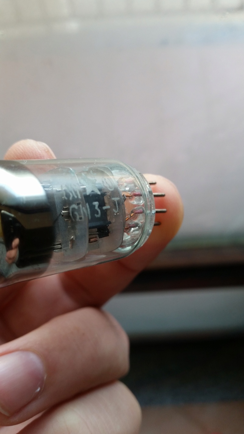
6N3 (not the rectifier tube lol) is the Chinese equivalent of the Russian 6N3P.
6N3 (not the rectifier tube lol) is the Chinese equivalent of the Russian 6N3P.
.. This is the valve with the original KIT ..6n3-J ...
6N3?
6N3, Tube 6N3; Röhre 6N3 ID21974, Half-Wave Vacuum Rectifier
I suspect you mean 6N3P
https://frank.pocnet.net/sheets/112/6/6N3PE.pdf
If you increase R8 to 1k2 that should reduce the gain. There is a mismatch though, 33k anode load working into a lower than 8k load. (47k load resistor in parallel with 10.4k).
2u2F and 510k, have you worked out the low frequency pass 3db point yet. Sub sonic!
220nF should be adequate.
Hello Sir ,
are not very practical with the valves, I did not understand this you say "" "There is a mismatch though, 33k anode working load into a load lower than 8k. (47k load resistor in parallel with 10.4k)" .... I have to reduce the resistance of the anode from 33k to 8 K? thank you.
It is an easy and quick way to improve dynamics, clarity and detail with this chinese pre-ampboard.
... Based on your advice, I changed how to see the schematic (values in red) .... I did not understand your advice "" There is a mismatch though, 33k anode working load into a load lower than 8k. (47k load resistor in parallel with 10.4k) ""
Since this modification have not detected a significant reduction Gain is, but the detail, the scene and the sound is much improved, ....... was reduced, however, the low sound range!
Since this modification have not detected a significant reduction Gain is, but the detail, the scene and the sound is much improved, ....... was reduced, however, the low sound range!
Take 1 step not two. Focus on 1 "problem" not two at same time.
You replaced both C2 and R8 and don't know what caused bass level to drop, AND make remark about gain not being lower, but detail improved.
I read in Jon's post that the low value of feedback resistor R5 (then 10k) is too low for RO2 to work properly, next you lowered resistor R5 further to 8k2. Further deteriorating situation for RO2 valve.
I suggest for now to forget about the too much gain part of your problem and first make amplifier work better, not affecting signal too much.
...you are right, one step at a time, I was wrong 😡...... I can go back to C2 and put back 2,2uF ... you say? .. while I did not understand about R5 .... I have to increase the value (already 8k2)? ...
You measured Voltages at different points ? Vdc coming from rectifiertube, plate voltages 5670's, maybe also cathode voltages 5670's ?
*can be very high DC voltages, so carefull, maybe using only one hand
*can be very high DC voltages, so carefull, maybe using only one hand
Last edited:
Now I would replace R2 by the 33k resistor that is now on plate RO2. I would use much lower value for plate RO2, 5k maybe. And I think R5 then can easier be like 20K. Biascurrents go up a little, if transformer is small maybe voltages will drop, I think you can test.
Maybe real tube people have better ideas.
Maybe real tube people have better ideas.
I just noticed you call schematics Buffer.jpg. You think you bought a no gain buffer and got a two gain stages preamplifier ?
no, ... I am convinced that you have bought preamps with Gain ...... this I think to be sure ...
- Status
- Not open for further replies.
- Home
- Amplifiers
- Tubes / Valves
- Preamp Hengpen-13 with 6N3 advice!!