HI all
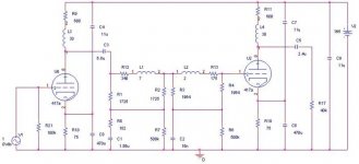
I just finish my LCR riaa stage.
I love it but it`s not still perfect.
I need a better bass, more robust and extended...
that is the only complain i have.
R9,R12,R13 and R11 are inductor DCR
On simulation, I have 1.2 Db riaa accuracy. I just don`t understand why my bass is not as good as my previous riaa project.
PS; I use sealed acid battery for PSU (B+ and heater) I expect my psu to have about 24ohm impedance (12battery in serie, about 2 ohm each)
Thanks
Attachments
Wow, that's what i call impressive!
Are the numbers next to the chokes Henry? 30H may be a bit low for a 417. What types of chokes are you using? They must be pretty well shielded if you don't complain of hum.
Bass? Some people may find 1.2db excessive. What did you use to simulate and calculate the riaa values? Have you tried adding capacitance and chokes in the PS?
I wish i had the guts to build one like that!
>Wow, that's what i call impressive!
Thanks,
>Are the numbers next to the chokes Henry? 30H may be a bit >low for a 417.
I run at 16mA. So -3db is 17hz. I don`t use bigger choke because i`m affraid to heve subsonic noise.
>What types of chokes are you using? They must be pretty well >shielded if you don't complain of hum.
With battery supply, i don`t have ANY hum!!!")
>Bass? Some people may find 1.2db excessive. What did you use >to simulate and calculate the riaa values?
Orcad capture lite (free on their official website)
Have you tried adding capacitance and chokes in the PS?
Should I?. If I add capacitance, that will be electrolytic one. I tend to don`t use them...
I wish i had the guts to build one like that!
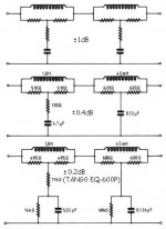
I greatly recommend to build a LRC type. that better to passive RC EQ. I changed the value of mine for fit the output impedance of my first stage (1.8K)
this is the original value from tango EQ.
martin
Thanks,
>Are the numbers next to the chokes Henry? 30H may be a bit >low for a 417.
I run at 16mA. So -3db is 17hz. I don`t use bigger choke because i`m affraid to heve subsonic noise.
>What types of chokes are you using? They must be pretty well >shielded if you don't complain of hum.
With battery supply, i don`t have ANY hum!!!
>Bass? Some people may find 1.2db excessive. What did you use >to simulate and calculate the riaa values?
Orcad capture lite (free on their official website)
Have you tried adding capacitance and chokes in the PS?
Should I?. If I add capacitance, that will be electrolytic one. I tend to don`t use them...
I wish i had the guts to build one like that!
I greatly recommend to build a LRC type. that better to passive RC EQ. I changed the value of mine for fit the output impedance of my first stage (1.8K)
this is the original value from tango EQ.
martin
Attachments
fdegrove said:Could it be you lose bass response because the LCR RIAA isn't terminated?
I wondered about that, but etalon90 says he ran a simulation on it. Mind you. 1.2dB error is rather large...
Hi,
Exactly.
I know that proper termination of the 600 Ohm ones is mission critical; put 620 Ohm instead of 600 Ohm to terminate it and you lose the entire RIAA curve along with it.
I see no reason why this wouldn't be the case with a 1K8 cell.
Either way it doesn't take much to find out and if it works fine this would be great news.
After all a 1K8 Ohm load is much easier to drive with valves than a measle 600R, right?
Cheers,
Mind you. 1.2dB error is rather large...
Exactly.
I know that proper termination of the 600 Ohm ones is mission critical; put 620 Ohm instead of 600 Ohm to terminate it and you lose the entire RIAA curve along with it.
I see no reason why this wouldn't be the case with a 1K8 cell.
Either way it doesn't take much to find out and if it works fine this would be great news.
After all a 1K8 Ohm load is much easier to drive with valves than a measle 600R, right?
Cheers,
fdegrove said:After all a 1k8 Ohm load is much easier to drive with valves than a measly 600R, right?
This is a common misconception (I've even found it on semiconductor manufacturer's data sheets). 600 Ohm meant driving from 600 Ohm, and terminating in 600 Ohm. In other words, the source actually saw a load of 1200 Ohm. (The source was always made to have almost zero output resistance, so that adding a series 600 Ohm resistor gave constant 600 Ohm output resistance with frequency and level.)
Hi,
O.K. I see the mistake.
For this particular implementation (LCR RIAA) g' would than be 3K6 which is still a very heavy load for anything but a xformer or CF to tackle, correct?
Which is why we almost invariably see a stepdown xformer after the driving stage in pro gear a la Pultech etc.
Any advice on how to best implement this LCR correction without resorting to esoteric xformers?
TIA,
(The source was always made to have almost zero output resistance, so that adding a series 600 Ohm resistor gave constant 600 Ohm output resistance with frequency and level.)
O.K. I see the mistake.
For this particular implementation (LCR RIAA) g' would than be 3K6 which is still a very heavy load for anything but a xformer or CF to tackle, correct?
Which is why we almost invariably see a stepdown xformer after the driving stage in pro gear a la Pultech etc.
Any advice on how to best implement this LCR correction without resorting to esoteric xformers?
TIA,
fdegrove said:Any advice on how to best implement this LCR correction without resorting to esoteric xformers?
I'm afraid not. You need a low working impedance, otherwise the inductors become unreasonably large. It really is the ideal place for a transformer - unless (just thought of it) you were to use an OTL headphone amplifier, perhaps with E55L or 6C45?
Perhaps. But it a gyrator would inevitably add noise which couldn't really be tolerated in the first stage of this design. If you added more gain before the equalisation, you could get away with it, but then you would have lost the appealing simplicity of the original design.
OK, fair enough. But since RIAA can be implemented simply and inexpensively with R and C, I guess I don't see the point of having inductances in there except for some esthetic ideal. Of course, I could say the same thing about the tubes, but I'd be run out of the forum on a rail.
Hi,
On the bright side, you could always buy ms Y a girator for her next birthday.
I hear they're excellent for making mayonaise...
Of course, I could say the same thing about the tubes, but I'd be run out of the forum on a rail.
On the bright side, you could always buy ms Y a girator for her next birthday.
I hear they're excellent for making mayonaise...
Hi,
Technically I don't see any.
From people that built a preamp using such a LCR correction I hear nothing but praise.
Comments like it sounds like that good old Decca without the flaws are not uncommon.
Making mayo isn't easy without the right utensils...
Cheers or should that be bon app...
what is the advantage of LC versus RC equalization?
Technically I don't see any.
From people that built a preamp using such a LCR correction I hear nothing but praise.
Comments like it sounds like that good old Decca without the flaws are not uncommon.
Mrs Y doesn't cook. Dr Y does.
Making mayo isn't easy without the right utensils...
Cheers or should that be bon app...
Attachments

SY said:OK, fair enough. But since RIAA can be implemented simply and inexpensively with R and C, I guess I don't see the point of having inductances in there except for some esthetic ideal.
I'll probably be run out of the forum on the same rail as you, but in a bridged T equaliser like this, the equalisation is actually being done by the CR networks, and the LR department is the complex conjugate that forces the impedance to be resistive. Or should be. To do it properly means matched impedances at either end.
Now, a 3k6 resistive load is a nasty load, and will cause 2nd harmonic distortion to rise, but it isn't as nasty as a reactive load that forces the loadline into an ellipse. That really causes distortion. So, yes, there could be a demonstrable technical advantage to LCR equalisation if implemented conscientiously.
That's interesting, and you've now earned more questions by being sucker enough to answer me.
Since in a typical tube phono stage we're swinging some really low voltages compared to what's dropped across the plate load and the tube (maybe a couple hundred millivolts compared to maybe a couple of hundred volts), how much distortion, more or less, is really coming from the tube pumping into the reactive load of a passive RC RIAA network? How much reduction, more or less, could be available by putting in these conjugate networks?
My first stage tube doesn't see anything like 3-4K from the following passive RIAA, it's something like 20-30K at minimum, and I don't think I've done anything out of the ordinary. If you think there might be an advantage to get the reactances out of the plate circuit, I could always direct couple the first stage to a cathode follower- cheaper and easier than all those inductors, and I don't have to lay awake nights worrying about using magnetic materials in the signal path.
SY said:That's interesting, and you've now earned more questions by being sucker enough to answer me.
Sigh. Rod for my own back...
Since in a typical tube phono stage we're swinging some really low voltages compared to what's dropped across the plate load and the tube (maybe a couple hundred millivolts compared to maybe a couple of hundred volts), how much distortion, more or less, is really coming from the tube pumping into the reactive load of a passive RC RIAA network?
There are whacking great signal voltages leaving the stage before equalisation! Remember, RIAA equalisation has a dynamic range of 39dB from 20Hz to 20kHz - and that's without considering the dynamic range of the recorded signal. RIAA pre-amplifiers are as challenging as microphone pre-amplifiers. RIAA design is a juggling act to try to encompass the dynamic range of LP (say, 60dB) plus the dynamic range of RIAA (39dB) = 100dB, without running into noise or headroom problems. It's why valves are ideal.
How much reduction, more or less, could be available by putting in these conjugate networks?
Very hard to say without designing an entire pre-amplifier with them in mind, but it might be worth it...
My first stage tube doesn't see anything like 3-4K from the following passive RIAA, it's something like 20-30K at minimum, and I don't think I've done anything out of the ordinary.
Yes, that's fairly typical.
If you think there might be an advantage to get the reactances out of the plate circuit, I could always direct couple the first stage to a cathode follower- cheaper and easier than all those inductors, and I don't have to lay awake nights worrying about using magnetic materials in the signal path.
Think current, rather than voltage. The cathode follower still has to swing current into the unpleasant load. It has lots of local negative feedback (am I allowed to approve of such a thing?), but it still has vertical excursions on its curves. Nevertheless, yes, a high current (perhaps 10mA) cathode follower can make sense for buffering an RIAA equalisation network - especially if the preceding stage has been optimised for linearity and uses an active load or weedy (but low distortion) valve such as 7F7.
- Status
- This old topic is closed. If you want to reopen this topic, contact a moderator using the "Report Post" button.
- Home
- Amplifiers
- Tubes / Valves
- my RIAA stage. Any comment