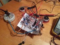
Finally got a few hours to lash together a design I've been playing with, and I am extremely proud of how it turned out. The very messy prototype is surprisingly hum free, and can be driven to 1.4w clip, but can sustain a clean 1.2w continuously, using a ~300 volt supply. My calculations point to around 2w would be possible at higher voltage around 400 or so without too much change.
Now here's the goofy parts- I am using Antek toroidal power transformers as outputs, and due to the low current and power, 10VA units work great, and are very affordable. In order to keep the current balanced, I'm using the garter bias arrangement, which works way better than you think it should, and at such low current and voltage is not a big loss at all having extra cathode resistors. I drop 9.2 volts across each 1k resistor, so my tubes are running at 282 volts, sitting at around 2.6w idle dissipation per triode, 5.2w per tube, not counting the heater. It's got NFB too, just to make everyone upset
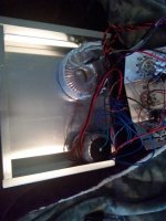
Here's a messy teaser pic of the first rig, but I'll get up a schematic soon. I've got an aluminum box coming tomorrow and will work on a layout for it too.
Now here's the goofy parts- I am using Antek toroidal power transformers as outputs, and due to the low current and power, 10VA units work great, and are very affordable. In order to keep the current balanced, I'm using the garter bias arrangement, which works way better than you think it should, and at such low current and voltage is not a big loss at all having extra cathode resistors. I drop 9.2 volts across each 1k resistor, so my tubes are running at 282 volts, sitting at around 2.6w idle dissipation per triode, 5.2w per tube, not counting the heater. It's got NFB too, just to make everyone upset
Here's a messy teaser pic of the first rig, but I'll get up a schematic soon. I've got an aluminum box coming tomorrow and will work on a layout for it too.
Attachments
Last edited:
I am using Antek toroidal power transformers as outputs...
How do these perform at bass frequencies (< 100 Hz) ?
Last edited:
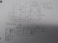
As promised, the schematic and more details. You may notice I'm not one for exotic parts values, I like easy and simple if they work well.
The power transformer used for the psu-
Antek AS-05T240, $28
The power transformers that I'm using as output transformers-
Antek AN-0105, $10
The primaries are wired in series, and the secondaries are wired in parallel. Since impedance ratio is the square of the turns ratio, 230/5= 16928 ohms for an 8 ohm load, 33856 ohms for a 16 ohm load. Output tubes are Russian (6H9C) 6SN7. While this sounds great and works fine at 8 ohms (especially considering we are using negative feedback to keep everything in line) it would likely work with better THD on a 16 ohm load. Since I plan on building a nice pair of speakers, I think they will be running 16 ohm in the long run. They will eventually drive either a pair of Karlsonator or Cornu style designs in my bedroom, depending on which sounds better once I get around to building some...
Input/phase inverter tube is a russian (6H9C) 6SL7, although a 6N1P, 12AT7, or similar would work as well. I arbitrarily set the feedback resistor at 15k, considering that I am running a 1500 ohm cathode resistor at the input stage, although I might play with increasing the feedback resistor to increase the overall gain. I found when plugging directly into my cellphone that the gain was a little low. I might try replacing the 15k with a 39k or 33k pair in parallel with a switch to swap them in and out to deal with different sources. The capacitors I used for the output stage bypass are 35 volt rated electrolytics from a local Radio Shack that is going out of business. Use whatever brand snake oil you prefer if you must.
Power supply is pretty basic, and built using parts on hand. The smaller caps are some film caps I have in my parts bin, electrolytic capacitors should work as well. Make sure you mind the DC bias for the heaters! On the next build I wil likely use a higher voltage secondary, as the AS-05T240 is only giving me 305 volts rectified. The Antek AS-05T280 would do very well in its place, and has a 280 volt secondary with a 260 volt tap. This would give more room to play around, and let you squeeze a little more power out of the outputs with just a few component changes.
Attachments
Last edited:
How do these perform at bass frequencies (< 100 Hz) ?
Excellent. Some very bass heavy music has no problem on these guys when played through an 8" celestion that I have on hand. I am not set up for any more testing than DMM or ear for now though.
A man after my own heart. Well done.
I went SE parafeed for my flea powered amp, but always fancied building a mini PP flea amp.
Shoog
Your Toroid 6080 experiments are what led me to try them out in this guy! Push pull just makes more sense to me, slightly more complicated, but worth the fuss IMHO. I've played with garter bias back when I was in love with the 6AS7G (which I still am) and it seemed like a natural way to go on a low power design. Garter bias truly does work extremely well, and sounds excellent. It seemed like a natural way to go for toroidal output stages to keep everything balanced without getting into active circuitry.
I like them so much, I'm going to order a few toroids for the five channel 6AS7G amp that I'm working on for the home theater system, but thats another story. Think this guy, but with an output stage B+ of 165 volts, garter bias with 330R resistors, 100 volt across each triode, ~100mA, and around ~32 volts of bias across each resistor. Hot, heavy, and wasteful, but it sounds very nice and works very well
Last edited:
Well, like a goof I left my circuit a little bit unoptimised. With a change at the input stage of just a little more negative grid voltage, I should be able to increase the gain and maximum swing available a bit. The cathode resistor will be changed out to 2700 ohms, with a corresponding change of the feedback resistor out to 27k. I want to leave in the option for less feedback, so I may experiment with something like a 33~39k feedback resistor(or a couple of resistors of 56~68k switching in parallel). I could always go with an LED and a small resistor underneath for feedback, and this would increase gain even further, so that might be my next experiment if I can find an LED in my bin that is close to the needed voltage. Of course the mail came right after I left for work, so I wont get to mock up the chassis until tomorrow.
Instead of 2 x 470 lytics with same if not better result you can use a single non-polar one between cathodes. For 2Wa 10 uF will be well sufficient, smth like 2 x Murata 4,7uF 50V WLCC would do.
I have had a similar SHAX flea power project on my breadboard singing for already 6 weeks, waiting for some parts to put it in final incarnation.
I have had a similar SHAX flea power project on my breadboard singing for already 6 weeks, waiting for some parts to put it in final incarnation.
Instead of 2 x 470 lytics with same if not better result you can use a single non-polar one between cathodes. For 2Wa 10 uF will be well sufficient, smth like 2 x Murata 4,7uF 50V WLCC would do.
I have had a similar SHAX flea power project on my breadboard singing for already 6 weeks, waiting for some parts to put it in final incarnation.
I've got a handful of 6~8uF film caps I may try in the cathode then. My 6AS7 garter bias arrangement used back-to-back 470uF caps, with a 1M resistor at the junction shunting to ground, and a nice 8uF film from cathode to cathode, and it worked very well in that application. Poor man's nonpolar cap of sorts
Yeah, back-to-back-with-1M I tried in my previous project, those were 1000uF, matched. I specifically tested this poor man's trio against a non-polar 82uF x 100V, the latter won giving slightly less THD, about 0.1 difference, no brainer.
82uF turned out be sufficient up to 10-12Wa output. The voltage should be twice of cathode Bias value for the particular used quiescent current.
82uF turned out be sufficient up to 10-12Wa output. The voltage should be twice of cathode Bias value for the particular used quiescent current.
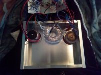
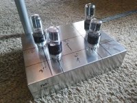
Got my chassis yesterday, and pulled out the tangled mess of wiring prototype to see how the transformers fit. The box is an aluminum 10x8x2.5" Bud industries AC-1418, I had some credit on Amazon, so I grabbed it. Looks like aa good size box, and if using smaller tubes with top mounted output transformers, you could probably squeeze an EL84 or similar push pull amp into it without too much fuss.
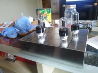
I see I will have enough room for sure, but unsure how to go with the transformer orientation. With such low power levels, would I be fine with the transformers all on the same plane, or should I plan on mounting the outputs sideways as shown? Sideways would be easy to do, and give more room.
Also, power switch will be one of these-

Would it be better to hug the chassis with the wiring the same way I would my heater wiring, tightly twisted, or would it be better to use shielded cable and just go straight to the front panel? I plan on putting the switch center left or dead center on the front panel.
I see I will have enough room for sure, but unsure how to go with the transformer orientation. With such low power levels, would I be fine with the transformers all on the same plane, or should I plan on mounting the outputs sideways as shown? Sideways would be easy to do, and give more room.
Also, power switch will be one of these-
Would it be better to hug the chassis with the wiring the same way I would my heater wiring, tightly twisted, or would it be better to use shielded cable and just go straight to the front panel? I plan on putting the switch center left or dead center on the front panel.
Attachments
In my spud I actually mounted the two OT on the same bolt stacked wise. No noticable crosstalk can be detected. These toroidals are robustly immune from stray pickups.
Shoog
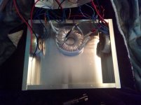
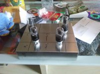
Hmmmm, something like the attached picture then? Maybe I can squeeze an IEC inlet in the ccorner between the trafo and the chassis...
Picture turned sideways for whatever reason
Attachments
Hmmmm, something like the attached picture then? Maybe I can squeeze an IEC inlet in the ccorner between the trafo and the chassis...
Picture turned sideways for whatever reason
Yep, works a treat.
Shoog
Oh man, this is the kind of project that makes diyaudio awesome. Thank you for sharing!
If you've got measuring gear, I'd love to know how those output transformers behave at the extremes. I've thought about this kind of thing several times (also inspired by Shoog's crazy exploits), though never with the micro watt tubes.
If you've got measuring gear, I'd love to know how those output transformers behave at the extremes. I've thought about this kind of thing several times (also inspired by Shoog's crazy exploits), though never with the micro watt tubes.
Oh man, this is the kind of project that makes diyaudio awesome. Thank you for sharing!
If you've got measuring gear, I'd love to know how those output transformers behave at the extremes. I've thought about this kind of thing several times (also inspired by Shoog's crazy exploits), though never with the micro watt tubes.
One of my goals for this project was that it needed to just work without adjustments, it needed to be reasonably affordable, and it needed to use easy to acquire and substitutable parts.
So far the cost is at-
Resistors- already had on hand, junkbox (maybe $2)
Capacitors- already had on hand, junkbox (maybe $5? Depending on how crazy you get)
Sockets- already had on hand, junkbox (about $7 shipped, eBay)
Chassis- $22 shipped (Amazon, mouser, digikey)
Transformers- $55 shipped (Antek)
Tubes- $21.50 shipped ($2.20 each before shipping, rutubes.com used for example)
Power switch- $3 shipped (Amazon)
IEC socket- already had on hand, junkbox ($2? I take mine from dead computer PSU)
RCA jacks- already had on hand, junkbox, ($2)
Speaker jacks- already had on hand, junkbox ($2)
$121.50 if my math is correct, not bad considering, but that's the amount you would be spending to just go grab everything now. The only parts I had to go out and buy specifically for this build are the output transformers, power switch, and chassis. Everything else I already had on hand, as the power toroid I had on hand from a project I switched directions on. I'm using Russian equivalent tubes and they work great at these voltages, but if you wanted to crank more current through the output or run much more voltage, I would go with 6SN7GTA/GTB types so you can run higher idle current at a higher supply voltage.
For anybody wondering, this would make a killer headphone amplifier, especially for power hungry 16-32 ohm headphones...
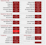
Bored at work, but have my laptop with me, so I spent a bit of time playing around with the Push-pull Amp Cad program from TubeCad. Interestingly, my estimates were pretty darn close! looks like just under a watt, and from previous experience, this program is surprisingly pretty accurate, usually gets most values within 5%. Both of these are running on 300 volt supply, and using a shared cathode resistor, but that shouldn't make a terribly large difference, and if anything the individual cathode resistors of the finished amplifier should give lower distortion than a shared resistor.
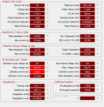
This was simmed using the 16928 ohm transformer values, and interestingly doesn't reduce 3H when doubling the transformer impedance. I of course will try to get real measurements once I am able, but it looks promising so far. I have a feeling once the feedback is wrapped around the little guy it will measure better than simmed. I've also attached the sim results from a 6V6 triode connected pair with an 8k OPT, and signal levels adjusted to give similar output power. Not too shabby for a single dual triode to do this well against the venerable 6V6 for a low power design. I will play with higher voltage too, as it looks like just around ~2 watt is possible with 375 volt supply. I might grab a pair of GTA type tubes to play with running them at higher dissipation, as the russian tubes are more or less equivalent to the 6SN7GT types, and not the higher spec GTA/GTB types.
This was simmed using the 16928 ohm transformer values, and interestingly doesn't reduce 3H when doubling the transformer impedance. I of course will try to get real measurements once I am able, but it looks promising so far. I have a feeling once the feedback is wrapped around the little guy it will measure better than simmed. I've also attached the sim results from a 6V6 triode connected pair with an 8k OPT, and signal levels adjusted to give similar output power. Not too shabby for a single dual triode to do this well against the venerable 6V6 for a low power design. I will play with higher voltage too, as it looks like just around ~2 watt is possible with 375 volt supply. I might grab a pair of GTA type tubes to play with running them at higher dissipation, as the russian tubes are more or less equivalent to the 6SN7GT types, and not the higher spec GTA/GTB types.
Attachments
Last edited:
In my flea-PP project I got 3rd almost disappearing with the output of about half watt per channel, but the tubes are smaller. At first I used the TALEMA toroids as OPTs, but they sounded acceptable ok with headphones only.
But then I wanted to make it able to drive speakers and came across the very inexpensive but well-German-made TrafoBlocks FL6/9 about $4 apiece on evilBay (took 4) incl shipping, and those produced about 0,3 non-distorted Wa on speakers - already enough for background listening at the office as that was the purpose.
I'll create the topic once I get evr together to some presentation level.
BTW Trafoblocks are C-core-like design (laminated though), i.e. identical primaries and secondaries well separated and 2KV hot-pot tested vs bifilar TALEMA's windings, think of this. No wonder these sounded better.
Last edited:
- Home
- Amplifiers
- Tubes / Valves
- 6SN7 push pull flea amplifier project