Nice guide! I believe that "R5- 1M and R5 1M5" should be "R5- 1M and R6 1M5". C1 is specified at 250V (rightly so) and C2-C3 are specified as "same as C1": but don't they require a voltage equal to the Vcc supply (290-300V) instead?
I am interested in the all-noval version. It would be great to fit two output tubes per channel, to build a parallel push-pull and use a standard output transformer meant for EL84/6V6. This kind of low power tubes may be spaced closer togheter.
I am interested in the all-noval version. It would be great to fit two output tubes per channel, to build a parallel push-pull and use a standard output transformer meant for EL84/6V6. This kind of low power tubes may be spaced closer togheter.
A few errors and the wording needs work, I'll work on it more tomorrow
I think an all noval version would be neat. It's a good excuse to grab some 6N6P too")
Never let an English major edit your work. One at the publisher had me inventing something I had no connexion with, all when I'd have been about 10 yrs old. How cool is that?
Luckily got that fixed before it went to the printer..
A few errors and the wording needs work, I'll work on it more tomorrow
I think an all noval version would be neat. It's a good excuse to grab some 6N6P too
I am a big advocate of the 6N6P. I built a little single ended spud for my wife a few years back. It uses a 70 volt line transformer from back when they had inductance. It's actually the amplifier that sits in our living room. I've also used them with a 10VA Antek 5+5 volt transformer in a CCS loaded parafeed push pull driven by gyrator loaded 6sn7 with a CCS on the tail as the phase inverter. The detail of that amp was phenomenal... way better than it should have been. It never got a real home, and had since been converted into a breadboard, and then the transformers used elsewhere. Still... that amp really stands out to me.
Attachments
More work on the guide! added some more pics, and a couple more spots have been reworded.
Anybody local to California that's in the Mountain View or Sunnyvale areas during the week, or the Antioch area on weekends? I'll give out a couple PCBs for anybody local to the SF Bay area who is willing to come grab a couple. I have a complete populated octal PCB with Russian 6N9S and 6N8S tubes I could also pass along for someone to play with if they have the relevant transformers (or would be willing to buy a set) to build up an amplifier. I have very little time but I'm willing to pass along some parts for those interested to play with
I believe I have 9 PCBs each of the octal and noval versions on hand.
Already found a couple formatting errors and typos, fixing it now
Edit- there we go!
Wow thanks, I've been breadboarding two circuits a month that I get from the forum, usually I have to read through 300 posts to find the least buggy schematic version! A PDF from the designer sure saves time. I hope to hook this one up soon with some carbonized glass 6SN7's I've been saving. If you are revising the PDF anyway, the wiring of the garter is a little hard to read with all the X jumper symbols hiding the wires, it's a little tight to see it right off.
Already found a couple formatting errors and typos, fixing it now
Edit- there we go!
Wow thanks, I've been breadboarding two circuits a month that I get from the forum, usually I have to read through 300 posts to find the least buggy schematic version! A PDF from the designer sure saves time. I hope to hook this one up soon with some carbonized glass 6SN7's I've been saving. If you are revising the PDF anyway, the wiring of the garter is a little hard to read with all the X jumper symbols hiding the wires, it's a little tight too see it.
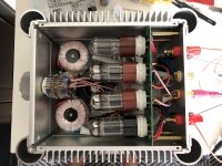
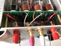
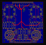
This is my take on the subject, all basic SMD parts, no matching of anything. Sounds very nice actually as desktop amp. I am planning to make another PCB for it with the nice THT parts, matched resistors, etc, and see what the difference will be
Thanks for all the ideas and inspiration!
Thanks for all the ideas and inspiration!
Attachments
Last edited:
Very nice!
Thanks, most of the credits go to you actually
BTW this is the circuit with one small capacitor between 6SN7 cathodes, without caps from cathodes to ground
As promised, the schematic and more details. You may notice I'm not one for exotic parts values, I like easy and simple if they work well.
The power transformer used for the psu-
Antek AS-05T240, $28
The power transformers that I'm using as output transformers-
Antek AN-0105, $10
The primaries are wired in series, and the secondaries are wired in parallel. Since impedance ratio is the square of the turns ratio, 230/5= 16928 ohms for an 8 ohm load, 33856 ohms for a 16 ohm load. Output tubes are Russian (6H9C) 6SN7. While this sounds great and works fine at 8 ohms (especially considering we are using negative feedback to keep everything in line) it would likely work with better THD on a 16 ohm load. Since I plan on building a nice pair of speakers, I think they will be running 16 ohm in the long run. They will eventually drive either a pair of Karlsonator or Cornu style designs in my bedroom, depending on which sounds better once I get around to building some...
Input/phase inverter tube is a russian (6H9C) 6SL7, although a 6N1P, 12AT7, or similar would work as well. I arbitrarily set the feedback resistor at 15k, considering that I am running a 1500 ohm cathode resistor at the input stage, although I might play with increasing the feedback resistor to increase the overall gain. I found when plugging directly into my cellphone that the gain was a little low. I might try replacing the 15k with a 39k or 33k pair in parallel with a switch to swap them in and out to deal with different sources. The capacitors I used for the output stage bypass are 35 volt rated electrolytics from a local Radio Shack that is going out of business. Use whatever brand snake oil you prefer if you must.
Power supply is pretty basic, and built using parts on hand. The smaller caps are some film caps I have in my parts bin, electrolytic capacitors should work as well. Make sure you mind the DC bias for the heaters! On the next build I wil likely use a higher voltage secondary, as the AS-05T240 is only giving me 305 volts rectified. The Antek AS-05T280 would do very well in its place, and has a 280 volt secondary with a 260 volt tap. This would give more room to play around, and let you squeeze a little more power out of the outputs with just a few component changes.
wow those are good prices on the transformers. thanks for the link!
Just keep in mind that they may not necessarily be the best choice for a high fidelity build, but as a basic build for background tunes they sound great. I haven't had the equipment to test the frequency response of them in the amplifier, but basic testing shows them to be good through the audio band in regular use.
If you want build something nicer I would recommend going to 10k transformers and doubling the load for 20k, but the cost will be much higher, of course
If you want build something nicer I would recommend going to 10k transformers and doubling the load for 20k, but the cost will be much higher, of course
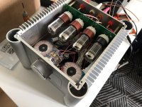
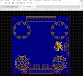
Sneak peak at the very early stages of the first revision... going to have a ground plane, more streamlined connections, and 100mm square. Noval only for the input tubes this time, and once this is up I'll work on noval output tubes, and a differential input version.
If anybody is interested in boards from the first batch let me know, I have several of each still left.
If anybody is interested in boards from the first batch let me know, I have several of each still left.
Attachments
Last edited:
Very nice!
Thanks for putting this together! I had been following along for some time with interest, and a little while ago received an AliExpress delivery of what was supposed to be 8K to 8/4 Ohm single ended output transformers, but they accidentally shipped 8K to 4/8 Ohm push-pull transformers instead. An 8 Ohm speaker on the 4 Ohm tap should give me 16K into 8 Ohms, so in the (lowish) range for your amp. These OPTs are tiny and specced for 3 Watts output and 30 mA. I am going to put this amp in the cue. Thanks again for your work on this!
You can always double up the output tubes- a friend built a version with dual output tubes on each channel, with independent coupling capacitors per tube so that they all bias up separately. He used the 6CG7 as outputs (nine pin version of the 6SN7) with 6N2p front end. If you didn't know any better you would think it was an EL84 build until you notice that the outputs are a bit shorter and have different internals. He used output transformers from an old magnavox console record player of 7-8k or so, and since the original speakers were 4 ohm it gives him 15k or so load with an 8 ohm speaker, for 30k per tube... Cool build.
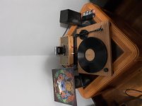
I still use my first build daily in the shed/shop while working on some woodworking projects.
I still use my first build daily in the shed/shop while working on some woodworking projects.
Last edited:
- Home
- Amplifiers
- Tubes / Valves
- 6SN7 push pull flea amplifier project