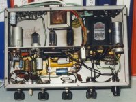
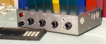
Betty Crocker Special PP 6BL7 3 Watts
Finally got back on this one, been looking at the PPP6080 I built 20yrs ago.
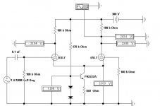
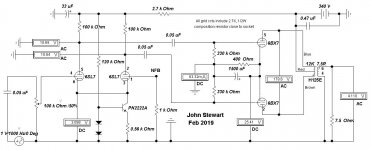
This iteration of the Betty Crocker uses a differential driver, something I've preferred for more than 20yrs. Equalization to the output is straight forward.
On this one I used a NPN cathode drain, the balance is very good. The schema is attached, the full schematic to be posted later. The 6SN7 vers performed a little better with this driver.")
More info to follow.
Finally got back on this one, been looking at the PPP6080 I built 20yrs ago.
This iteration of the Betty Crocker uses a differential driver, something I've preferred for more than 20yrs. Equalization to the output is straight forward.
On this one I used a NPN cathode drain, the balance is very good. The schema is attached, the full schematic to be posted later. The 6SN7 vers performed a little better with this driver.
More info to follow.
Attachments
PP 6BX7 Amplifier
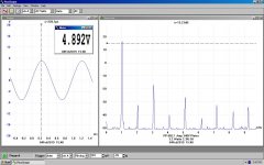
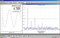
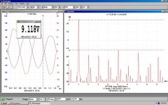
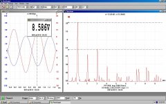
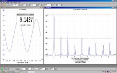
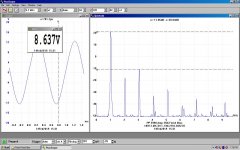
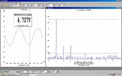
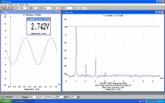
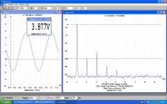
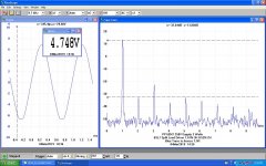
Here are the results for the PP 6BX7 version of the amplifier. Power output at clipping is just over 3W, same as the 6BL7 version. Both are limited by the maximum plate dissipation of 12W for these tubes.
Distortion results are shewn for both one & three watts into a 7.5R load resister. There are very few harmonics above the 5th all the way up to 3W. Clipping stars at about 3.2W. Another result shews the performance of the driver (blue trace) superimposed on the output (red).
I found the zero signal standing current measured was not the same as the simulation indicated. I believe that to be caused by the very simple model used by the simulation software to work as a triode.
The actual standing cathode current when running a 260V PS is 19.1V / 0.4K or 48 mA. That is the operating point set so that dissipation limits of the 6BX7 are not exceeded. Did the same thing for the 6BL7 version.
The internal resistance of the amplifier as seen by the speaker is 3.16 R. About 0.5R of that is due to the OPT. A different OPT would yield different results. As is, the Damping Factor is 2.37, typical for triode amplifier running without NFB.
With the Hammond 125E OPT the 3db down frequencies are 26 Hz & 25 KHz.
I prefer this version of the amplifier for the following reasons. Firstly, it runs on a relatively lower voltage power supply, a plus for reasons of safety. Rather than an expensive tubephile power transformer, one of the industrial 120/240V power transformers could be used to supply the B+. A full bridge rectifier of silicon diodes or half diodes & half FW vacuum rectifier are possible.
If a vacuum rectifier were to be used a 6X5GT would do. And has a similar appearance to the other tubes, some folks might prefer.
The power transformer in the bridge mod is somewhat more efficient then a CT HV supply. The entire secondary winding is used all the time. Not so for the FW CT version, something designers call ‘Utilization Factor’.
For a chassis built for stereo a 6AX5GT rectifier would work well.
Still need a heater transformer.
Attachments
Member
Joined 2009
Paid Member
With the Hammond 125E OPT the 3db down frequencies are 26 Hz & 25 KHz.
Dang, that's pretty reasonable. The 125E and ESE gets looked down on by many folk but it doesn't seem to measure too bad - price
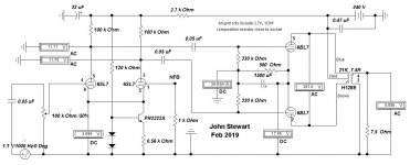
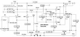
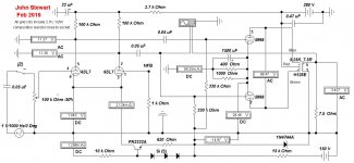
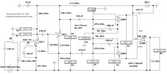
erformance is good.Somehow the schematic for the 6BX7 vers got left out. So here it is.
Triodes always drive OPTs better than pentodes. A triode is a voltage source, much like what comes out of the wall. So many OPT look good in triode ccts.
Driven by a pentode, LF rolloff depends on the load. Without local NFB, the response simply follows the speaker system impedance vs freq plot.
Triodes always drive OPTs better than pentodes. A triode is a voltage source, much like what comes out of the wall. So many OPT look good in triode ccts.
Driven by a pentode, LF rolloff depends on the load. Without local NFB, the response simply follows the speaker system impedance vs freq plot.
Attachments
Cool developments!
Maybe I should do a set of PCBs for a differential version too? It would be very simple and the symmetry would give many a warm-and-fuzzy
Sorry I've been quiet for a while. No real development in my stuff for a while, and have been using my spare time to work on my other hobby, aquariums and aquarium LED lighting. I've been drawing up a family of PCBs for constant current LED drivers
I got a bonus at work and will be using some of the cash to send out PCBs to those waiting patiently for them, and to order some of the new designs for the noval push pull "spider amplifier" and noval "flea SE" boards.
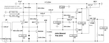
Just noticed the 6BX7 schematic posted is an older version. So here is the final.
I like this amp more than the others tried. Very straight forward. And it will tolerate a variety of OPTs that provide the correct loading. PS looks easy & cheap. 6BX7s used to be much cheaper than 6SN7s.
Not exactly a flea amp but worth a look.
3W doesn't seem like much but that is what runs in my workshop all the time. Its a 6AQ5 with about 20 db NFB. My home grown tiny amp now 51yrs old.
Attachments
Member
Joined 2009
Paid Member
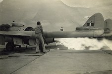
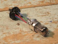
All too true. I've been somewhere in hitech for 70 yrs if I include working on military aircraft. The electrical systems on that thing in the photo. Starting often created lots of fire. The engine is an early version of Whittles original, uses a centrifugal compressor. Now all is axial flow.
Attachments
Betty Crocker Special with a PP 5998 Output
For the sake of completeness I've added this one for the curious. It clips smoothly at 11W. Needs a -ve supply for the 6SL7. Will add the info on how to do that simply later.
For the sake of completeness I've added this one for the curious. It clips smoothly at 11W. Needs a -ve supply for the 6SL7. Will add the info on how to do that simply later.
Attachments
-
 PP 5998 Amp 11 Watts OPT Taps 1-5.JPG133.5 KB · Views: 76
 -
 PP 5998 Amp 10 Watts OPT Taps 1-5.JPG131.1 KB · Views: 161
 -
 PP 5998 Amp w 15V Neg Drain.JPG89.3 KB · Views: 200
 -
Betty Crocker 5998 Version on the Bench.pdf225 KB · Views: 72
-
Betty Crocker 5998 Version.pdf247.3 KB · Views: 70
-
5998.pdf300.4 KB · Views: 72
More on the PP 5998 & a Simple Negative Supply
Partial Fixed Bias
I’ve been thinking about partial fixed bias for several years, so here it is. There was already a minus 15V zener supply on the chassis, so the 5998 grids have been removed from common & connected to that.
The power triode cathode resistor needs to be adjusted to 280R. A 1K connected in parallel with the existing 400R resistor adjusts the standing cathode current to 100 mA. Total plate dissipation is just under 25 watts, the spec limit for the 5998. A pair of separate cathode resisters of 560R properly bypassed would improve output stage current balance.
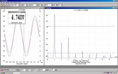
For the distortion tests I took the rapid increase of the 5th harmonic to be the limit. There is a smooth overload beginning at 11 Watts.
The partial/fixed cathode bias cct could be used with the 6BX7 version of this cct.
A survey of common high mu twin triode voltage amplifiers indicates a 12BZ7 would be an improvement over the 6SL7. I’ve put together an adapter to do that. And 12BZ7s are in my stash.
Negative Bias Supply Refer to Figure 6
A simple negative supply for the differential tail can be created by using the current pulses in the center tap negative return lead of the DC supply. For many years I had inserted a 10R resister into the lead to the HV CT in order to monitor peak current in the rectifier(s) & transformer.
By increasing the 10R resister to 100R, it is possible to create a simple negative supply for biasing & so on. In the schematic the voltage pulses caused by the current in the B+ supply to the rest of the circuit are picked off by the 1N4007 & stored in C112, an electrolytic capacitor. A small 560R resister & 14V zener do the rest in the example circuit.
More results in a few days.
Partial Fixed Bias
I’ve been thinking about partial fixed bias for several years, so here it is. There was already a minus 15V zener supply on the chassis, so the 5998 grids have been removed from common & connected to that.
The power triode cathode resistor needs to be adjusted to 280R. A 1K connected in parallel with the existing 400R resistor adjusts the standing cathode current to 100 mA. Total plate dissipation is just under 25 watts, the spec limit for the 5998. A pair of separate cathode resisters of 560R properly bypassed would improve output stage current balance.
For the distortion tests I took the rapid increase of the 5th harmonic to be the limit. There is a smooth overload beginning at 11 Watts.
The partial/fixed cathode bias cct could be used with the 6BX7 version of this cct.
A survey of common high mu twin triode voltage amplifiers indicates a 12BZ7 would be an improvement over the 6SL7. I’ve put together an adapter to do that. And 12BZ7s are in my stash.
Negative Bias Supply
Refer to Figure 6 A simple negative supply for the differential tail can be created by using the current pulses in the center tap negative return lead of the DC supply. For many years I had inserted a 10R resister into the lead to the HV CT in order to monitor peak current in the rectifier(s) & transformer.
By increasing the 10R resister to 100R, it is possible to create a simple negative supply for biasing & so on. In the schematic the voltage pulses caused by the current in the B+ supply to the rest of the circuit are picked off by the 1N4007 & stored in C112, an electrolytic capacitor. A small 560R resister & 14V zener do the rest in the example circuit.
More results in a few days.
Attachments
-
 PP 5998 Amp w Partial Fixed Bias Schematic.JPG91.9 KB · Views: 238
 -
 PP 5998 Amp w Partial Fixed Bias One Watt.JPG126.7 KB · Views: 84
 -
 PP 5998 Amp w Partial Fixed Bias Clipping.JPG125.1 KB · Views: 538
 -
 PP 5998 Amp w Partial Fixed Bias 10 Watts.JPG125.6 KB · Views: 532
 -
 PP 5998 Amp w Partial Fixed Bias 3 Watts.JPG126.1 KB · Views: 554
 -
 IMG_4002 Adapter 6SN7 pinout to 12AU7 pinout 10C 20B.jpg160.2 KB · Views: 562
 -
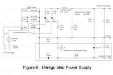 Figure 6 Unregulated Power Supply.jpg67.6 KB · Views: 560
Probably biased too far off. What does the cct look like?I did a combination of fixed bias with 9V batteries, and an LM317 based CCS in the cathode. Worked but had BAD notch distortion at the transition (crossover distortion?).
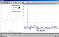
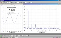
Here are the results for the PP 6BX7 vers of this amp. Still using the Hammond 125E OPT it clips at about 3 watts on a 250V PS. OK for a small amp. At no signal the total plate dissipation is 11.5 Watts. The 6BX7 cathodes are separately biased. For out of spec tube sections of +/- 10% this hookup reduces the unbalance plate current to 2%.
The driver is still the 6SL7 as used on the original. But not sure if Ling meant the two sections to be direct coupled or cap coupled. For the direct coupled version neither of the triodes operates in the best mode. So to get large output to the following grids AC coupling solves that problem. Since this amp is not meant for NFB, cap coupling is not a concern.
Seems odd but looking at the distortion at clipping actually goes down a bit for 2H & 3H. But that is replaced bu a spectrum of higher order harmonics.
During work on the PP 5998 vers I tried the 6SL7 in a differential connexion with an NPN transister for the cathode tail. The gain was somewhat less, but the distortion was also about one half of this version. Gain shewn is from the 6SL7 grid to the 7.5R load.
Attachments
Now *that* is a really nice circuit. So many of these threads seem to come from folks struggling to make a marginally designed circuit work well. We should be pointing to yours as an example of one done right. Perhaps you would share the differential input version as a modern improvement.
All good fortune,
Chris
All good fortune,
Chris
Can someone talk me through how the jhstewart9 schematic is using garter bias? I know the thread title doesn't reference garter bias but that was the initial design. I'm interested in what jh has done (and the concertina seems well put together) but it kinda seems like a very different project. Or has this thread moved on past garter bias? Just trying to figure this out.
He's not.
The original design used garter bias so as to be able to easily balance currents in the affordable toroidal PT as OPT.
If using actual OPTs, the balance isn't as important, and higher efficiency is realised.
Here's another idea I just came up with.
12B4 push pull. Ra-a=5k, Ik=30ma, Ipeak=87ma B+=170V, Vp-p=28V. Pout=3W, 1.2% 3rd harmonic.
Carlp,
The Garter Bias circuit in this thread is originally mentioned in post #1. The first schematic in this thread with Garter Bias is post #6.
I am not going through all 356 posts in this thread to find any jhstewart9 schematics that have the Garter Bias circuit. But his most recent schematics in this thread do Not have Garter Bias.
Any thread that has 356 posts may have several posts that are off part of, or all of the original post's subject(s).
I am not a real fan of Garter Bias, it has not been necessary in my circuits. I have found that reasonably matched tubes (do not have to be a perfect match) will have very similar currents if they have matched individual self bias resistors. Use individual bypass capacitors if you need the gain (they have to be individual caps so the resistors can be 'individual' for each cathode).
With Garter Bias you may get matched currents. But if one tube starts to run away, it will cause the other tube to have the same high current as the run away tube. One tube goes bad, and tries to bring the other tube with it.
If you use fixed bias and set them to identical voltages for each tube grid, you almost always will not get matched currents (unless the tubes are perfectly matched). Inexact tube match requires individually adjusted fixed bias for each tube.
Look at the 2 most recent jhstewert9 schematics.
Post 351 combination bias, uses identical voltage fixed grid bias, plus shared cathode self bias resistor (therefore cathodes with identical voltage self bias).
Post 354, I can not quite make out what he is doing.
jhstewart9,
Schematic post # 354:
Can you clue us in, please? Is the schematic correct?
Here's another idea I just came up with.
12B4 push pull. Ra-a=5k, Ik=30ma, Ipeak=87ma B+=170V, Vp-p=28V. Pout=3W, 1.2% 3rd harmonic.
Interesting. I've been thinking about the 12B4 as output tube a bit lately.
I think the garter bias issue is just a focus of mine and I've conflated it with this thread. I'll try not to do it again!Carlp,
I am not a real fan of Garter Bias, it has not been necessary in my circuits. I have found that reasonably matched tubes (do not have to be a perfect match) will have very similar currents if they have matched individual self bias resistors. Use individual bypass capacitors if you need the gain (they have to be individual caps so the resistors can be 'individual' for each cathode).
With Garter Bias you may get matched currents. But if one tube starts to run away, it will cause the other tube to have the same high current as the run away tube. One tube goes bad, and tries to bring the other tube with it.
The thing is, the 6SN7 is a twin triode as is the 6AS7 (the tube I'm mostly interested in and that drew me to this thread). Twin triodes don't give you much control over matching. I don't know much about the 6SN7 but the 6AS7 is notorious for non-matched sections, hence my interest in ways to handle that - one of which is garter bias.
I've got a partially wired 6AS7 version of Ling's amp but have had no time to continue it. But I'm emerging from my obligations, so hoping soon to re-start. Then I'll think more carefully about jh's and others in this thread.
Member
Joined 2009
Paid Member
- Home
- Amplifiers
- Tubes / Valves
- 6SN7 push pull flea amplifier project