buffer circuit
Ok, so does a buffer circuit increase the strength of the signal from the preamp to the amp, as compared to a completely passive preamp? (due to the low output impedance).. Also, what is unity voltage gain? Is that an increase in the output of the preamp voltage? So, ultimately what does the buffer circuit do for the sound? I have seen a few preamp projects on this forum which are very simple (like the thread a little below this one called 12B4A linestage)- they consist of a volume control, input, and output, plus a buffer circuit based on the 12B4A tube, which is supposed to be very neutral and detailed with little coloration. How would something like this compare to the sound of a full-blown preamp, which has various gain stages? Thanks a bunch
Dave
Hi,
Compared to a passive preamp which is just a volumecontrol, a buffer behind it transforms the output impedance seen by the next stage to a much lower value making it easier to transmit the signal correctly as the input capacitance of the pot and interconnect cable are not seen by the input of the amplifier, it is essentially isolated from the following stage.
Basically this is a 1:1 relationship, what goes in goes out. In reality the "gain" is slightly less as the tube buffer will present a small insertion loss, .95 to .98 at best.
In practice this is nothing to worry about as the previous stage, mostly a CDP, will have ample gain.
Even the 12B4A preamp has more gain than you'll ever need from a line preamp. The 12B4A being a very linear tube you have every opportunity there to make one of the best preamps ever, bar none.
Naturally the endresult will depend on the execution of the design, PS and passive components used.
Hope this helps,")
Ok, so does a buffer circuit increase the strength of the signal from the preamp to the amp, as compared to a completely passive preamp? (due to the low output impedance)..
Compared to a passive preamp which is just a volumecontrol, a buffer behind it transforms the output impedance seen by the next stage to a much lower value making it easier to transmit the signal correctly as the input capacitance of the pot and interconnect cable are not seen by the input of the amplifier, it is essentially isolated from the following stage.
Also, what is unity voltage gain?
Basically this is a 1:1 relationship, what goes in goes out. In reality the "gain" is slightly less as the tube buffer will present a small insertion loss, .95 to .98 at best.
In practice this is nothing to worry about as the previous stage, mostly a CDP, will have ample gain.
How would something like this compare to the sound of a full-blown preamp, which has various gain stages?
Even the 12B4A preamp has more gain than you'll ever need from a line preamp. The 12B4A being a very linear tube you have every opportunity there to make one of the best preamps ever, bar none.
Naturally the endresult will depend on the execution of the design, PS and passive components used.
Hope this helps,

Re: ECC85 or ECC88?
Hi,
The question should be: why and what for do you need a buffer ? The schematic of the stage you have attached is usually used as a voltage gain stage. It requires more supply voltage than usual CF (cathode follower) and is more difficult to implement than CF. It is like active load in plate of the lower tube (constant current source).
You can read a lot on the stage here:
SRPP Deconstructed
... and on buffers:
Power buffers @ tubecad
Tyimo said:...could I use it for tube buffer? ...
Tyimo
Hi,
The question should be: why and what for do you need a buffer ? The schematic of the stage you have attached is usually used as a voltage gain stage. It requires more supply voltage than usual CF (cathode follower) and is more difficult to implement than CF. It is like active load in plate of the lower tube (constant current source).
You can read a lot on the stage here:
SRPP Deconstructed
... and on buffers:
Power buffers @ tubecad
Hi Yagoolar!
Thanks for your answer!
I would like to use a buffer between the CD and a SS amps (Aleph5, JLH, Hiraga) to get "warmer" tube sound!
I am looking for a simple, but effective tube buffer circuit, possible with ECC88 and on low voltage. I found that ECC85 circuit somewhere in the forum, but I forgot where. (The schematic was colled:tube buffer ECC85.)
Tyimo
Re: need more info
Szia,
Yes, it's buffer, with gain about 1. But I think, that the lower part is not really necessary. Keep the upper, and use 22-27kohms cathode resistor to the -85V rail. The other half of the valve can handle the other channel. This cathode follower is simple, and universal. You can try some different valves, and You have to modify the heaters only.
Sajti
Tyimo said:Hi!
I have this schematic somewhere from the forum, but I forget already
Thanks
Tyimo
Szia,
Yes, it's buffer, with gain about 1. But I think, that the lower part is not really necessary. Keep the upper, and use 22-27kohms cathode resistor to the -85V rail. The other half of the valve can handle the other channel. This cathode follower is simple, and universal. You can try some different valves, and You have to modify the heaters only.
Sajti
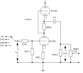
"I have this schematic somewhere from the forum, but I forget already ) from which thread. Could somebody give me more info abaout it? Is it a buffer or a preamp?"
Hi thats my schematic based on JoeRasmussen's Valve buffer. I am using mine as a preamp with unity gain. Works great and sounds excellent. The power supply is very critical. Something like a split rail RCRCRC will do the trick. I am using 4 UL85 single diode rectifiers to get the split supply. The bottom 1.2K resistor is a mistake and should be more like 220K (try a few values until you like the sound, your looking for a voltage drop of about 1.6V across the resistor). I also tried a green LED to bias the bottom valve, but eventually found the sound a bit strident and went back to the resistor. That was when I discovered the mistake with the bias resistor.
I say try the schematic as is, Joe Rasmussen spent a good deal of time designing the principle of this circuit and he obviously thought it worthwhile using the bottom Constant Current Source over a basic resistor. I tried a basic resistor biased version (Joes published valve buffer). A version with a Mosfet at the top and a bias resistor at the bottom, and finally the version with the valve at the bottom and the Mosfet at the top. I definately found the final version the most satisfying (but there were many other variables which make a definative statement difficult).
Joe even went to the extent of replacing the top Mosfet with a valve in one of his preamps and said it sounded even better.
No compromise !!!!
Shoog
) from which thread. Could somebody give me more info abaout it? Is it a buffer or a preamp?"Hi thats my schematic based on JoeRasmussen's Valve buffer. I am using mine as a preamp with unity gain. Works great and sounds excellent. The power supply is very critical. Something like a split rail RCRCRC will do the trick. I am using 4 UL85 single diode rectifiers to get the split supply. The bottom 1.2K resistor is a mistake and should be more like 220K (try a few values until you like the sound, your looking for a voltage drop of about 1.6V across the resistor). I also tried a green LED to bias the bottom valve, but eventually found the sound a bit strident and went back to the resistor. That was when I discovered the mistake with the bias resistor.
I say try the schematic as is, Joe Rasmussen spent a good deal of time designing the principle of this circuit and he obviously thought it worthwhile using the bottom Constant Current Source over a basic resistor. I tried a basic resistor biased version (Joes published valve buffer). A version with a Mosfet at the top and a bias resistor at the bottom, and finally the version with the valve at the bottom and the Mosfet at the top. I definately found the final version the most satisfying (but there were many other variables which make a definative statement difficult).
Joe even went to the extent of replacing the top Mosfet with a valve in one of his preamps and said it sounded even better.
No compromise !!!!
Shoog
Hi,
Te power supply I used was quite simple.
As I said I made a bridge rectifier out of four UY85 valves (dirt cheap). I then put them into a split supply. Each rail was filtered by;
a small inductor from a bass speaker crossover (has little effect, but should slow down inrush current)
next a 270 ohm resistor
next a 220 uf cap to earth
next a 22 ohm resistor
next another 220 uf
next another 22 ohm resistor
another 220 uf cap.
Finally I have an o.47uf mkp cap between the rails.
I have had no issues with overstretching the rectifier valves and the thing has been running for about 5months now.
Ther raw AC supply is a little difficult to pin down as I have used a 6.3V transformer to supply two speaker line output transformer, which step the supply up to about 100V per side. Its very difficult to source suitable 70-100V transformers.
This supply is very quiet.
At first I tried replacing the middle filter cap with a capacitance multiplier, but this had a bad effect on the sound, and so I removed it with no ill effects.
Any more questions, just ask.
Shoog
Tyimo said:Sajti!
A tápodban hány Wattos az R6-7 ellenállás? 0.5-3W?
Köszi!
I would like to wish for every DIY-ers Happy Easter!
Tyimo
Szia,
miután még sztereóban sem folyik rajta 10mA-nél nagyobb áram, ezért 0.5W-1W bőven elég. Én 1W-ost használtam
sajti
Re: ECC85 or ECC88?
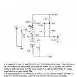
That circuit is called a super linear cathode follower SLCF.
To the best of my knowledge it was pioneered by
Allen Wright and Joe Rassmussen of Vacuumstate.
Cheers,
Terry
Tyimo said:Hi!
Could somebody give me some info about the attached schem: could I use it for tube buffer? Is it possible to use the circuit with ECC88 tube too? What would be the lowest voltage for?
Thanks
Tyimo
That circuit is called a super linear cathode follower SLCF.
To the best of my knowledge it was pioneered by
Allen Wright and Joe Rassmussen of Vacuumstate.
Cheers,
Terry
Shoog said:Hi,
Te power supply I used was quite simple.
As I said I made a bridge rectifier out of four UY85 valves (dirt cheap). I then put them into a split supply. Each rail was filtered by;
a small inductor from a bass speaker crossover (has little effect, but should slow down inrush current)
next a 270 ohm resistor
next a 220 uf cap to earth
next a 22 ohm resistor
next another 220 uf
next another 22 ohm resistor
another 220 uf cap.
Finally I have an o.47uf mkp cap between the rails.
I have had no issues with overstretching the rectifier valves and the thing has been running for about 5months now.
Ther raw AC supply is a little difficult to pin down as I have used a 6.3V transformer to supply two speaker line output transformer, which step the supply up to about 100V per side. Its very difficult to source suitable 70-100V transformers.
This supply is very quiet.
At first I tried replacing the middle filter cap with a capacitance multiplier, but this had a bad effect on the sound, and so I removed it with no ill effects.
Any more questions, just ask.
Shoog
Shoog,
To put things into perspective as the literature mentioned to operate the vavles in the proper cascode manner, which pin does the 1K input resistor connectes to ?
regards,
will.
Let's say we have a CDp with a typical Zout of 50K and an amplifier with the same Zin.What's the purpose of using some buffer stage?Why does this change so much the tonal quality-which ever huppens, but I can't explain why.Is this just because of the elimination of capacitance that wires and pot injects?
- Status
- This old topic is closed. If you want to reopen this topic, contact a moderator using the "Report Post" button.
- Home
- Amplifiers
- Tubes / Valves
- buffer circuits