Re: Re: ECC85 or ECC88?
It's an adaption of a Tektronix scope input stage, but with a MOSFET substituted for one of the tubes.
Terry Demol said:
That circuit is called a super linear cathode follower SLCF.
To the best of my knowledge it was pioneered by
Allen Wright and Joe Rassmussen of Vacuumstate.
It's an adaption of a Tektronix scope input stage, but with a MOSFET substituted for one of the tubes.
"To put things into perspective as the literature mentioned to operate the vavles in the proper cascode manner, which pin does the 1K input resistor connectes to ?"
I can't remember off the top of my head exactly which pin to attach the input to.
When I say the correct cascode manor what I mean is, one half of the triode pair is designed to go at the bottom, and one is designed to go at the top. This keeps the cathode to heater voltages within range. An examination of the data sheet will tell you which is which. In order to make it work in my circuit you need to tie the heaters to the negative rail, so placing it at -85V potential. If done this way there will be no heater hum with AC heater supplies.
I also have since reduced the the bottom triodes grid stopper resistor to 1K.
I hope that helps.
Shoog
Thanks Sajti!
Thanks Terry!
Shoog: "There are copies of the Musical Fidelity X10D circuit on the net somewhere..."
I was looking for the Musical Fidelity X10D valve buffer schematic on the NET, but I didn't find yet... :-(
Do you remember where did you see? I listened an original one and it worked very well!!
Greets: Tyimo
As a matter of fact I can point you to a copy of it right now
http://ampchipdiy.com/phpBB2/viewtopic.php?t=633
There you go.
Have fun.
Shoog
http://ampchipdiy.com/phpBB2/viewtopic.php?t=633
There you go.
Have fun.
Shoog
Re: Re: Re: ECC85 or ECC88?
Actually Allen got that out of the HP service manuals (he used to work for HP), but you will find it in Tek stuff too
dave
SY said:It's an adaption of a Tektronix scope input stage, but with a MOSFET substituted for one of the tubes.
Actually Allen got that out of the HP service manuals (he used to work for HP), but you will find it in Tek stuff too
dave
Shoog said:I personnally wouldn't like to run this circuit at anything less than +/-50V, preferably +/-80V or higher. This is where getting a suitable transformer becomes a real issue.
Shoog
I agree. My buffer was just playing with the E88CC tubes. I had 2x24V/15W transformer, and I want to build something with it. My experience, that this buffer sound good. The only disadvantage is that it can handle the output voltage up to 5-6V without significant distortion.
I made same buffer with +/-100V, and there was no problem, up to 30V. But You must be careful with the planning of this circuit. Due the high PSU voltages, You need slow start for the PSU, or very good output muting, to avoid -100V peak output when You switch on...
sajti
"You must be careful with the planning of this circuit. Due the high PSU voltages, You need slow start for the PSU, or very good output muting, to avoid -100V peak output when You switch on..."
Valve rectification sorts out all of these issues.
I'am not certain we are all talking about the same circuit at this stage !
Shoog
Valve rectification sorts out all of these issues.
I'am not certain we are all talking about the same circuit at this stage !
Shoog
Hi Shoog!
I was asking about Sajti's paralleled tube buffer's PSU.
I know that tubes like the higher voltage, but I interested for low voltage tube amps. Ernõ Borbély designed some low voltage tube circuits with great succes. (Also with ECC88)
But, thanks any way for your helps!
Greets:
Tyimo
I was asking about Sajti's paralleled tube buffer's PSU.
I know that tubes like the higher voltage, but I interested for low voltage tube amps. Ernõ Borbély designed some low voltage tube circuits with great succes. (Also with ECC88)
But, thanks any way for your helps!
Greets:
Tyimo
external PSU question
Hi!
I would like to build an external PSU for my buffer like the MF X10-D has: the transformator is not in the buffer's case, only the rectifiers and caps etc.
The question is : how could I get a symmetrical +/- 24-34VDC from a simple (not symmetrical, +/0) 24 or 48VAC transformer? The MF X10-D has an interesting method, but I would like to build a passive PSU and not regulated.Like Sajti recommended to his buffer.
Greets:
Tyimo
Attachments
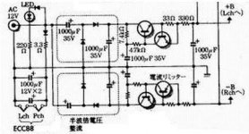
Hi Tyimo!Hi!
Could somebody give me some info about the attached schem: could I use it for tube buffer? Is it possible to use the circuit with ECC88 tube too? What would be the lowest voltage for?
Thanks
Tyimo
What is the anode voltage + B =?

thank you!
- Status
- This old topic is closed. If you want to reopen this topic, contact a moderator using the "Report Post" button.
- Home
- Amplifiers
- Tubes / Valves
- buffer circuits