Im wanting to build a tube amp for my turntable. I have robbed parts from an old rca console stereo. I plan to use the tubes, PT, and OPT's from that unit. I like this schematic, seems pretty simple. I would just like a little input on the bias circuit and what the pot is for in the power supply circuit. Or should I just take the schematic for the RS203A amp and rebuild it with a preamp using the 12ax7a's.
Attachments
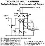
The 25K pot is for output tube bias voltage adjustment.
But this circuit uses a single-ended EL34 - which old RCA console used EL34 in class-A? And can you really get 20W class-A from a lone EL34 (6CA7)? (ETA: Mullard data sheet here claims Pout of 11W in Class-A @ 300V. 20 watts seems like a real stretch..
But this circuit uses a single-ended EL34 - which old RCA console used EL34 in class-A? And can you really get 20W class-A from a lone EL34 (6CA7)? (ETA: Mullard data sheet here claims Pout of 11W in Class-A @ 300V. 20 watts seems like a real stretch..
Last edited:
The 25K pot is for output tube bias voltage adjustment.
The bias supply diode is shown BACKWARDS!! Along with the 2 polarity reversed capacitors following it.
Don't trust that schematic.
Last edited:
The bias supply diode is shown BACKWARDS!! Along with the 2 polarity reversed capacitors following it.
Don't trust that schematic.
Good catch, there. Now that you mention, there are other wonky things as well. Like, the fact that the EL34 g1 & g2 connections are swapped, though the pin nos. are correct.
Any idea what the other circuit is about? Seems unrelated..
Any idea what the other circuit is about? Seems unrelated..
I think the RCA RS203A amp was in the console, and he wants to add that
RCA preamp circuit in front of it.
Or should I just take the schematic for the RS203A amp and rebuild it with a preamp using the 12ax7a's.
Can you post the RS203A schematic? The output transformer arrangement seems a bit unusual, compared to basic SE stereo output designs.
What sort of cartridge do you have in your turntable?
Can you post the RS203A schematic?
Here's what I found.. Not sure why it's marked "Columbia C-1014-T", but RCA would have been RCA/Columbia at this time, IIRC.

The output transformer arrangement seems a bit unusual, compared to basic SE stereo output designs.
Now, this is RCA, and it's safe to assume that the engineering works out OK.. But yes, that opt xfmr setup is bizarre.
Post #7 is a stereo amp using a transformer matrix method.
The push pull transformer secondary upper and lower taps referred to its center tap is
L + (-R), and -L + (R). The single ended transformer secondary is L+ R.
The PP and SE transformers have to be perfectly matched then:
Combining the secondaries you get 2L and 2R.
Getting a PP and a SE transformer to match in frequency response and DCR seems like a very hard task.
Failing to match them would at least cause the signal to move from Left to Right (or Right to Left) according to the frequency of the music, not to mention variable damping factors, distortion, etc.
Might this have been an engineering exercise to get a student his masters degree?
I would prefer using 2 single ended transformers and no transformer matrix wiring. Just wire them from the 6BQ5 plates in the classical way. And wire the feedback from the respective secondaries to the respective 12AX7 cathodes. Simple is sometimes good.
I bet that would work better.
I believe im going to keep it simple and just follow the original schematic for my first one just to get a feel for things. I would however like to change the preamp and make it 2 stage. How much benefit would it be if any. I just feel using one 12ax7a in halves is not reaching full potential, maybe im wrong.
Just wire them from the 6BQ5 plates in the classical way. (...) Simple is sometimes good. I bet that would work better.
Good grief, just about anything would be 'better'. Can you think of even one, good reason that they would have done that?
Was there a large surplus of the PP xfmrs, and a shortage of the SE type? I don't see any reason at all to design a circuit like this from the ground-up.. don't you think it must have been done to meet a specific price point, or something along those lines?
Do you mean rebuild the RS203A or build the first schematic you posted?I believe im going to keep it simple and just follow the original schematic for my first one just to get a feel for things.
I would however like to change the preamp and make it 2 stage. How much benefit would it be if any. I just feel using one 12ax7a in halves is not reaching full potential, maybe im wrong.
Are you going to use this amp only with your turntable?
My recommendation for a first build would be an amp that is 'looking for' a 2v input (CD player, etc). Phono stages are harder to keep 'quiet', so I'd suggest a separate phono preamp (possibly SS?) to match your cartridge.
I have no interest in vinyl, but I think issues with equalization have to be dealt with in the phono section.
I'd also buy a couple of (cheap) SE output transformers rather than using the ones you salvaged. You can give/sell those OTs to somebody building guitar amps or use them yourself for mono projects.
The PT from your salvage should be useful.
Anyway, thanks for introducing me to that unusual output section and thanks to 6A3 for explaining how it works!!
")
The RCA / Columbia amp schematic is made for Crystal or Ceramic Phono Cartridges.
It actually has plenty of gain for that type of cartridge, but does not have enough gain for a magnetic cartridge (and does not have proper equalization for a magnetic cartridge).
If your signal source is always a CD player or AM / FM tuner, there is plenty of gain for that.
But the tone controls at the input will not do anything wth those signal sources, because they are designed to work with the high impedance output of a crystal or ceramic cartridge.
Often, the terms "gain" and "output power" are misunderstood, they are not the same thing.
More gain of an extra preamp in front will not increase the maximum power that the 6BQ5 tubes are capable of. It only makes it so that you get to a certain power level versus a certain setting of the loudness pot. And too much gain can add noise, and can distort if the signal to the preamp is too large.
If somehow you have unusually low level signal sources, extra gain of a front preamp will allow you to get to the max power of the 6BQ5s.
If you only use CD and Tuner as signal sources, you can simplify the input circuit by eliminating everything in front of the Loudness control, and changing the loudness control to a 100k dual audio taper pot (volume control). That is because the treble and bass controls will not work with those signal sources.
You can connect the top of the loudness pot to the signal in; and connect the loudness pot wiper directly to the 12AX7 Grid, and eliminate the 6.8 meg resistor there.
The 6.8 Meg is too large versus the 12AX7 spec. Connect the loudness pot bottom to ground of the schematic.
Unfortunately, the modules K1 and K2 are frequency tailoring, and affect phase. The negative feedback resistor and capacitor from the transformer, and the RC network in the
12AX7 takes into account those modules, and the particular transformers that were used.
If you do not have the original K1 and K2 modules, the original Push Pull transformer, and original Single Ended transformer, this circuit will be hard to make work and be stable and not oscillate, etc. because of those factors.
If you do not have those original parts, it would be a matter of 2 Single Ended output transformers, a 12AX7 plate resistor, and an RC coupling network between the 12AX7 plate, and the 6BQ5 grid.
The feedback network would need to be tailored to the new combination of parts (most likely just a parallel Resistor and Capacitor. The series RC at the 12AX7 would go away.
Then the amplifier circuit would be very simple, the most complex thing would be adjusting the RC feedback network.
I agree, it would be simpler to use a known schematic, i.e. 12AX7 and SE 6BQ5, or 12AT7 and SE 6BQ5 in pentode mode with negative feedback. Two half of one 12AX7 could be used to drive the 6BQ5.
I seem to remember that Heathkit and Eico had such amps, but I do not remember the
input tube they used. There are other such schematics out there too.
If power was not an issue (very efficient loudspeakers), the 6BQ5s could be wired in triode mode, no feedback required. Costas Sarris has a schematic for a 6922 and 6BQ5, and there are so many others with tried schematics, many that are quite simple.
I guess there was some confusion due to my lack of knowledge. I wanted to build the 20 watt amp in the first diagram but have learned a little more in my research on building amps. Around 5 watt is going to be more realistic considering im wanting to reuse the parts from the console. I have speakers with good sensitivity around 92db.
What I want to do is to build a nice chassis from hardwood and reuse the PT, OPT's, (2) 12AX7A's, and (2) 6BQ5's for a simple SE stereo amp for my vinyl only. I don't need any tone control just volume. Is a simple diagram using 1/2 of a 12A per channel fine or is using the 2 stage preamp diagram overkill going into the 6's.
Since I learn best by doing thats why I mentioned building my amp based on the factory diagram. I can visually look at how it works while building. Once I get my feet wet and learn more I can build more complex and more powerful projects. Besides, I hear this hobby is very addictive. Thanks for all the help, I'm excited to get my project going theres just soo much to read and study.
@cg45acp
Are you confusing EL84 and EL34 types? I ask, as your parts on-hand are 6BQ5 (EL84) but so far, you keep offering EL34 (6CA7) designs. While both are pentode / beam-power types, the EL84 and EL34 are distinctly different tubes, with the EL34 being physically much larger and capable of twice the power of the EL84.
If all you're wanting is a 15WPC stereo amp, the time-tested combination of 2x 12AX7 (or 12AT7) and 4x EL84 (6BQ5) is a truly safe bet. The rectifier is typically a 5U4GB. You'll also have a much easier time finding compatible PP opt xfmrs for EL84 versus SE versions.. though SE versions obviously do exist. If you could find a second identical (or close) chassis, then you'd have a pair each of PP and SE opts.. enough for one each PP and SE stereo amps.
Here are two classic 12AX7 / EL84 circuits that are known to work just fine:
Fisher 20A (detail):

Eico HF-81 (detail):

Are you confusing EL84 and EL34 types? I ask, as your parts on-hand are 6BQ5 (EL84) but so far, you keep offering EL34 (6CA7) designs. While both are pentode / beam-power types, the EL84 and EL34 are distinctly different tubes, with the EL34 being physically much larger and capable of twice the power of the EL84.
If all you're wanting is a 15WPC stereo amp, the time-tested combination of 2x 12AX7 (or 12AT7) and 4x EL84 (6BQ5) is a truly safe bet. The rectifier is typically a 5U4GB. You'll also have a much easier time finding compatible PP opt xfmrs for EL84 versus SE versions.. though SE versions obviously do exist. If you could find a second identical (or close) chassis, then you'd have a pair each of PP and SE opts.. enough for one each PP and SE stereo amps.
Here are two classic 12AX7 / EL84 circuits that are known to work just fine:
Fisher 20A (detail):
Eico HF-81 (detail):
Last edited:
I want to encourage you to build an amplifier.
Decide what you can build, depending on what parts you have, or will obtain.
If the parts are all from the Columbia / RCA? amp, it has one Single Ended transformer, and one Push Pull transformer. That is going to be a problem, unless you build that exact amp.
Or, with the addition of 1 Single Ended transformer, you can build 2 single ended amps of a different design (and I highly recommend purchasing and using 2 SE transformers of the same exact type).
If you use the original power transformer, it will power the filaments and B+ requirements of one 12AX7 and 2 6BQ5s. It will not power 2 EL34s, and 2 12AX7s. We do not want the transformer to burn up.
You might be able to get close to about 5 watts using the 6BQ5s in Pentode mode, which will require negative feedback to work well.
Using 6BQ5s in Ultra Linear mode requires output transformers that have the ultra linear tap, but the SE transformer you have does not. The UL might work OK without negative feedback, but could benefit with it. But you are talking about 2 new output transformers.
Here is another idea:
Use the push pull transformer you do have, and Triode Wire the 6BQ5s in push pull.
Then build a phase splitter with the 12AX7 to drive the 6BQ5s. Because they are in push pull, you get more power than a single triode wired single ended. But you should not require negative feedback to get good performance.
You can use the power transformer you have.
Now you have a Mono amplifier.
If you like it you could duplicate it, purchasing a power transformer, push pull transformer, 12AX7, and 2 6BQ5s. At that time you would probably want 2 identical push pull transformers, and no longer use the one from the Columbia.
I sometimes wish I was there, because it is easier to discuss, show amps I have or have built, and discuss the trade-offs. I returned to tube amps years ago by starting with an existing amp, and modified it per my own design.
please forgive my ignorance, there is nothing in the schematic i have indicating both PP and SE transformers in this console. I was under the impression that PP required twice the number of tubes per channel. I only have reading material to help me along not experience.
A RIAA preamp should let me use a turntable with a tube amp.
A RIAA preamp should let me use a turntable with a tube amp.
Attachments
- Status
- This old topic is closed. If you want to reopen this topic, contact a moderator using the "Report Post" button.
- Home
- Amplifiers
- Tubes / Valves
- First Home Stereo Amp