A 60W @20Hz for 1.2-1.3T max induction transformer made with C-cores for a 50W amplifier is just a waste.
First it's a waste because the amp only delivers 50W; Second, C-cores do not suffer high distortion like EI laminations and can be used without problem at induction up to just below the on-set of saturation (1.6T with M6 and 1.8T with Hi-B approx.); Third, the previous point is even more acceptable being at 20Hz.
No "sensible" music will require more power in 20-30Hz range than higher frequencies. Hence if 50W are required to the amplifier in the 20-30Hz frequency range it will have to deliver more power at frequencies right above which is impossible if its max undistorted power is 50W.
30Hz is the best practical frequency to specify power rating for OT's unless it has to be used to listen to sinusoidal waves, elephants' infrasonic communications, earthquakes and so on....
I once recorded a piano concerto (with lots of low frequency notes including A0's that are 27.5 Hz) with two microphones at the same time: one without filter and one with low frequency cut-off at 35 Hz. No one was able to tell the difference in listening mode with both full range speakers and head-phones.
Finally with 8 mH leakage inductance and the core size one will need for those specs at low frequecy (I think no less than about 3.5 Kg) I strongly doubt one will get 100 KHz first resonance. More likely 50-60 KHz if everything will be optimized in the best possible way.
...I once recorded a piano concerto (with lots of low frequency notes including A0's that are 27.5 Hz) with two microphones at the same time: one without filter and one with low frequency cut-off at 35 Hz. No one was able to tell the difference in listening mode with both full range speakers and head-phones. .....
Hi there 45: After reading your comment above, ran to the living room and sounded Ao (25.5 hz) on the piano, then C# (34.6478 hz) and since there is no 35hz note, D1 (36.7081), I could clearly hear the difference in the notes. Then consulted with wife (violin and viola musician) and she confirmed my observations. ...regards, Michael
Hi there 45: After reading your comment above, ran to the living room and sounded Ao (25.5 hz) on the piano, then C# (34.6478 hz) and since there is no 35hz note, D1 (36.7081), I could clearly hear the difference in the notes. Then consulted with wife (violin and viola musician) and she confirmed my observations. ...regards, Michael
That filter didn't remove notes but just reduced their level by few dB's being first order. I did that because I was not sure about mic saturation. Put that into a musical program and tell me if you can spot a difference.
I am determining which output transformer to build for a Push-Pull 50 watt amplifier.
Not looking for a what is the best but instead a discussion of the pro's and con's of each option. Take this thread wherever you want as long as it's informative.
- What are the strengths and weaknesses of choosing a good C-Core? EI-core? - How significant is the inductance peak EI-cores have at 50% power? C-cores peak in inductance at 100% power correct?
- M3 or M6 strengths? I notice Hashimoto's C-cores (too expensive for me) use M6 core for their outputs. If I go Onetics I can choose M3 or M6 cores. Would it be wiser to go for M6 and go to a higher level of winding quality such as level three? Or the added expense of M3 and level 2 quality?
- Do larger output transformers lose anything in quality of sound? I came across a well respected user on this forum claim that the larger output transformers sound like a wet blanket was over them. That smaller outputs such as 10w PP sounded much clearer.
Thanks
You might find this thread interesting - particularly Cerrem's posts.
To avoid being "that guy" care to critique this for best results before I fire off an email for a quote to AE-Europe? I don't want to under-specify but I'd rather not tell them how to do their job and have a sub-par product. I will of course ask them what core materials they stock in addition to M6X.
1) 70W at 30Hz
2) 4.3K primary, 43% UL. 4/8 Ohm secondary.
3) Bandwidth (10 – 150,000 Hz) -3db minimum
4) Minimum inductance 200H, need to be measured also at low signal level, e.g. 1V/100 Hz
5) Double C-Core
6) Insertion loss <= 0.2 / 0.2 dB
Unsure about these.
7) Leakage inductance <= 8.5mH.
8) Resonant frequency > 100 KHz.
9) Nomex or teflon insulation between layers? Unsure if they use better materials. Should I specify?
10) Why would I not want split bobbine/symmetric winding?
Seems interesting if I ever build a SE amp. Thanks
1) 70W at 30Hz
2) 4.3K primary, 43% UL. 4/8 Ohm secondary.
3) Bandwidth (10 – 150,000 Hz) -3db minimum
4) Minimum inductance 200H, need to be measured also at low signal level, e.g. 1V/100 Hz
5) Double C-Core
6) Insertion loss <= 0.2 / 0.2 dB
Unsure about these.
7) Leakage inductance <= 8.5mH.
8) Resonant frequency > 100 KHz.
9) Nomex or teflon insulation between layers? Unsure if they use better materials. Should I specify?
10) Why would I not want split bobbine/symmetric winding?
You might find this thread interesting - particularly Cerrem's posts.
Seems interesting if I ever build a SE amp. Thanks
Last edited:
To avoid being "that guy" care to critique this for best results before I fire off an email for a quote to AE-Europe? I don't want to under-specify but I'd rather not tell them how to do their job and have a sub-par product. I will of course ask them what core materials they stock in addition to M6X.
Hi, Pegasus123,
Please e-mail specification exactly as I posted, since professional winders understood better precise numbers rather range of possibilities or directions.
Flux density in my post IS correct and not waste of anything. PP transformers are always subjected to some DC imbalance of several mA (unless you use BIAS servo). Considering large number of turns this creates considerable DC flux, that's why extra headroom needed.
Nomex and teflon film have much lower dielectric constant compared for example to Kapton, thus one can decrease stray capacitance and resonant frequency.
Split bobbin / symmetric winding have its own pros and cons. It decreases stray capacitance yet leakage inductance between each half of primary and secondary is going up because different coil length. In this particular case split bobbin is not a key parameter.
Since you are ordering product twice expensive compared to average, its obvious this is credit for extra quality. Manufacturer may discount some of my specs, e.g. 80KHz resonant frequency, 50W/20 Hz @ 1.2T, and so on. This is still acceptable. All of them have typical winding diagrams for widespread models, and 60W/4.3K UL for KT88/6550 is very common. Thus, if you don't like something, you still have a chance to sell it at reasonable price.
I looked at the schematic of Pete Millett Engineer's amplifier. After assembly with different transformer you will need to optimize (for min overshoot / ringing) NFB capacitor C1 / 33pF with square wave and variable capacitor from the old radio connected in series with 0.1 - 0.2uF film cap.
PS. Googling "USA tube transformer manufacturer" brought some (surprisingly few) items. Chris Merren (Cerrem) mentioned before seem to have his own Merren Audio, Kandkaudio USA carries stock of Lundahl Sweden and possibly can order custom units, BudP (Bud Purvine / Onetics) also member of this forum. Basically you can post another thread here and Audiokarma titled "Please suggest output transformer winder in USA". This may save you some shipping and custom cost. Good luck !
It is not well specified Pegasus.
First, serious transformers manufacturers do not measure inductance at 100Hz.
Inductance is usually better measured at 20Hz-to-50Hz max.
Second, Volts applied are (usually) referred to primary so 1V is really a very small output of the order of 0.25 mW in your case. IME, it is not convenient because the core you need to also get 0.2 dB loss will be unnecessary big and expensive. Why don't you buy a Hashimoto HW100-5 straightaway? 1284$ for a pair...call for special price!
It is expensive but unlike many other OT's it will have a good re-sale value. You will never find one of these at popular price.....
http://www.tube-amps.net/images/Hashimoto_Specs/HW-100-5_1024.jpg
If you still want 200H at 1V primary voltage then frequency response with 10Hz @-3dB doesn't make any sense because inductance will be huge for 1W output (i.e. about 66V rms at the primary in your case). FR is usually measured at 1W output. That will be the case even if you had a source impedance of 100 Kohm. In fact if you have a source impedance of 100K, 200H inductance for 4.3K primary load F-3dB=3.2Hz! Lower source impedance means even lower F3 of course...
If you pick a good quality core material (including M6X) there is no need to specify inductance. Specifying the power at a given low frequency leaves no escape. Enough turns will be needed to cope with that power and inductance will be high (more than enough) anyway.
Forget specifying leakage inductance and other details if you don't know where they come from....just give a reasonable number for high frequency response.
Last edited:
Forget specifying leakage inductance and other details if you don't know where they come from....just give a reasonable number for high frequency response.
I had oscillation problems with transformer having -3dB HF response around 60KHz. Leakage inductance was something about 11 or 12mH - didn't remember. Coped that with awkward snubbers. With similar and 8.5mH no workaround required.
Transformer measured 60H inductance at 1V/100 Hz (with standard LCR meter) will scale to hundreds of H at higher signal levels anyway. One of my previous posts explains why.
45 likes to post endless objections, if Poppilin pops out thread will be hopelessly drowned.
Another good transformer for your circuit is the Plitron 2100-SSCR. Again 1060 CAN$ for the pair which is much cheaper than Hashimoto (810 US$?)...
http://www.plitron.com/wp-content/uploads/2010/05/2100SSCR.pdf
It is specified as 2K for 4 ohm load. You can certainly use it with 8 ohm load to get 4K. Of course power rating will be halved.
As the power bandwidth is 14Hz-117KHz (-3 dB) it means that the OT is capable of 50W @14Hz with 4 ohm load and thus the nominal 100W power is available from 20Hz. If used with 8 ohm load that will be 50W @ 20Hz. Just right!
Using it with 8 ohm will reduce power loss from 0.26 dB to 0.13 dB.
Frequency response and oscillations depend on leakage inductance, stray capacitance and source impedance.I had oscillation problems with transformer having -3dB HF response around 60KHz. Leakage inductance was something about 11 or 12mH - didn't remember. Coped that with awkward snubbers. With similar and 8.5mH no workaround required.
What you are missing is that with those specs you wrote I don't believe you will get capacitance so low to get 100 KHz resonance with 8.5 mH leakage inductance, especially if the secondary must be grounded. Frequency response is not even a good indicator where resonance is as it can easily happen that resonance is perfectly damped and FR extends (flat) well beyond first resonance. Transformers have multiple high frequency resonances but usually only the first needs to be taken care of. Phase response is needed....
Anyway, when the first resonance Q is not ideal and fb is applied it can be compensated. The Hammond doesn't go beyond 40 KHz in any case and it works.
First, me and Popilin are friends. Second, I only object what I think is objectionable. If you don't like it don't read....45 likes to post endless objections, if Poppilin pops out thread will be hopelessly drowned.
Last edited:
AJT, the answer is: it depends! It also depends on turns and frequency.
All other things being equal EI saturates first.
Saturation in EI cores starts to happen before the nominal value given in datasheets (i.e. when the average induction is around 1.3-1.4T). The field inside the core is not so uniform as in C-cores and there will be small volumes saturating while most of the core is still fine. Increasing induction will make these volumes grow and eventually reach overall saturation. To avoid this 1.2-1.3T is typically the induction limit for quality transformers.
Quality C-cores (if they are not I do not bother and use EI) can work up to 1.6T -1.8T, depending on the grade. Down to user to decide if that induction limit has to be at 20Hz or 30Hz or even bit more......
A minor detail is that generally the stacking factor for EI cores can be (if everything is done right) a bit better. If well put together the effective core area is 95% of nominal size vs 90-92% of C-cores.
You can compensate for lower Bmax with more turns but this will result in higher copper loss. Not necessarily higher leakage inductance (despite the fact the shape already gives worse figures for EI) because one can increase the number of windings. Increasing windings will of course increase capacitance but overall the first resonoance is shifted up (and so also better FR, typically) because if m is the number of interfaces between primaries and secondaries leakage inductance decreases with the second power of m (i.e. m^2) and stray C increases with m. So the product gets smaller.
Power loss within 0.7-0.8 dB is generally considered acceptable for HiFi use although can be a limiting factor in low power amps....
Increasing the core area for EI cores is easier and cheaper if space is no problem. That also gives more winding volume and lower copper loss.
A minor detail is that generally the stacking factor for EI cores can be (if everything is done right) a bit better. If well put together the effective core area is 95% of nominal size vs 90-92% of C-cores.
Two other minor details are that due to the ability to alternately stack the laminations EI-cores can be made to have a smaller gap than C-cores and the point you make about saturation beginning earlier in EI-cores only holds true for grain oriented materials.
dave
Toroidal cores are not in the list. Why?
Attachments
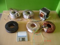
They are. See post n.50.Toroidal cores are not in the list. Why?
With minor differences (in practical use), GOSS toroidals can be included in the same class of C-cores.
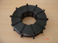
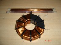
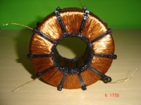
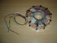
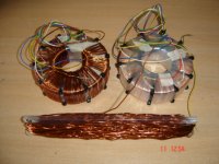
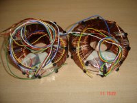
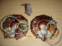
Did you make those in the pictures?
I refer to the first post. The post doesn't mention toroidal (Except you are using another name for them).
Yes, I made them turn by turn. 3000 + 3000 with derivation for UL at about 33% (1000 turns), and 160 for the secondary, to match 6Ω speakers. But they aren't the only I made, I made several more including power transformers for 275VDC at choke mode input. Again, turn by turn hand made.
Yes, I made them turn by turn. 3000 + 3000 with derivation for UL at about 33% (1000 turns), and 160 for the secondary, to match 6Ω speakers. But they aren't the only I made, I made several more including power transformers for 275VDC at choke mode input. Again, turn by turn hand made.
Of course Dave, it's a discussion about GOSS since the beginning and numbers are referred to it.
thanks.
The whole goss caveat always seems to get left out of the "superiority" of c-core propoganda much like people insisting that toroids do not have air gaps and toroidal power transformers must be wide bandwidth
carry on..
dave
thanks.
The whole goss caveat always seems to get left out of the "superiority" of c-core propoganda much like people insisting that toroids do not have air gaps and toroidal power transformers must be wide bandwidth
carry on..
dave
Actually, as you are reading now, have you ever had any chance to work with Radiometal 4550 or Super Radiometal (50%)?
Last edited:
- Status
- This old topic is closed. If you want to reopen this topic, contact a moderator using the "Report Post" button.
- Home
- Amplifiers
- Tubes / Valves
- Output Transformer - C-Core or EI; M3 or M6 core?