no disrespect, but that is just me, i will only accept results that i have verified myself...
maybe one day i will try it and when that happens i will come back with my findings...
after all it is the outcome that matters in the end....
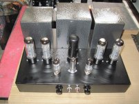
the picture i posted is just to illustrate what i do when i wanted to do a bridge,
a tube-silicon combination.....
as i make all my power traffos that i use in my builds, i have forgone center tapped
secondaries, i even use voltage doublers too....
maybe one day i will try it and when that happens i will come back with my findings...
after all it is the outcome that matters in the end....
the picture i posted is just to illustrate what i do when i wanted to do a bridge,
a tube-silicon combination.....
as i make all my power traffos that i use in my builds, i have forgone center tapped
secondaries, i even use voltage doublers too....
I really do appreciate everyone imput and respect that is shown to each other in thus thread. I really hope other readers are learning as much as I am going through this thread. I am posting the link to the build and pics/ schematics of the amp we are discussing.
I am confident there will be criticisms and advice one this. I have made changes...one being replacing most resistors with 720V resistors.
Well here it is, ready for the comments and any concerns/ critiques. No hum BTW from the power supply or amp.
.
http://www.diyaudio.com/forums/tubes-valves/281314-new-build-geraldine-se-amp.html
Last edited:
but one thing though, i will never argue with success, if it works, it works....
if it fails, we discover why, if it runs we still discover why....
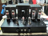
about 4 years ago, i made an el34 parallel set amp, tube rectified and
used the el84 in triode mode....
if it fails, we discover why, if it runs we still discover why....
about 4 years ago, i made an el34 parallel set amp, tube rectified and
used the el84 in triode mode....
Attachments
")
thankyou, on another note, i was given a 2a3 amp that was anemic sounding...
i rewired it, gave it a new opt, a tamura clone, the winder got the data
from rewinding burnt out tamuras....
i replaced the #26 dht preamp with a trioded 12hl7 and presto,
the owner was all smiles as he took it home....
that modification netted me with about 4kgs of parts, making that amp
a bit lighter...
Violating IFRM during the time that it warms up is even worse than during normal run-time, because the cathode of the rectifier is only half-warm and cannot give full current capacity. And when there has been arc-overs like this, the cathode will be damaged, and further arc-overs are more likely.
^ this.
As cathode heats, one small region becomes emissive first and carries all possible cathode current effectively operating in saturation. This small region thus self heats, so becomes more emissive, so gets hotter and so on. End result can be local damage to the cathode, release of cathode material into the cathode-anode space and a flashover.
Key is to be nice to rectifiers during warm up, limit current.
LD
Yes, even when there is no arc-over, violating the specs will dramatically shorten the life of the rectifier.
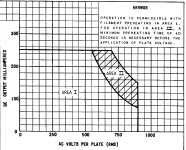
Sometimes the relationship between allowable current & voltage limits, in the case of warmed-up vs. cold cathode are given expressly in the data sheets. This is from 5R4GY:
Sometimes the relationship between allowable current & voltage limits, in the case of warmed-up vs. cold cathode are given expressly in the data sheets. This is from 5R4GY:
Attachments
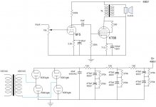
I have attached the power supply questioned in this thread. I did this rather than readers having to go through the thread I posted.
This has been a huge education... one I wish I had years ago....It would have life easier. Luckily, I have not built many amps.
Further simulations show that Thomas and Rod are correct. Everything looks good if the simulation collects data after 2 seconds. However, you miss all the fun of watching the amperage go through the roof.
I have the heaters tied to HV. I will disconnect them.
Attachments
What I find interesting, is that there seems to be so much emphasis on low impedance power supplies. I understand this for low voltage, high current amps- especially class AB and B class. Overkill just seems to be the norm...
I'm going for simply enough, in terms of current, capacitance and impedance it will be interesting to hear the results...and if I'm wrong...won't be the first time...nor the last.
I am interested in making an amp using higher voltage, (550V+), low current, high impedance OPT's. I will be using a max of 110mA total...including preamp, and VR tubes. My goal is less than 85mA for entire 2 channel amp...I'm only going for 4-5W per channel.
Would it be in my best interest to have a power supply with a little more impedance to keep the current under control? I'm looking at using lower value capacitors, even if more filter stages are required. I would just keep the last capacitor large enough to handle the transients.
Last edited:
As I can see, the first cap (440VAc) is too small insulated for 460VAC in the traffo's output. Why not to try a higher WV one?
The first Cap is a motor run capacitor...big. Its rated up to 620VDC. They are good for more than that. I thought that the amp would never reach that voltage during normal operation. This was prior to me simulating without load on the power supply. I simulate the power supplies under no load as well to see how high the voltage would go if a tube or speaker were to become disconnected.
I was under the belief that motor runs would be better for the first cap. I think I will do two electrolytic's in series as I won't have room for a higher WV motor run.
BTW, be careful when looking at the ratings on oil filled caps. I bought 2 5uf caps that said 600V... I assumed it was 600Vac.... they are actually 600Vp (peak).
Would it be in my best interest to have a power supply with a little more impedance to keep the current under control?
Unless you want to have some certain 'sag' in a guitar amplifier, you'd better eep the PSU's impedance as low as possible. Keeping current under control is a task of the amplifier design itselves.
Best regards!
- Status
- This old topic is closed. If you want to reopen this topic, contact a moderator using the "Report Post" button.
- Home
- Amplifiers
- Tubes / Valves
- 6DE4 Flash