How about this one, at least it's different
Perhaps the hole thing is a mistake, but not the schematic ( it only looks wrong)
Mona
I think the use of a 12AX7 is a terrible choice for the output, in any case. A 6DJ8 or 6CG7/6SN7 would be a far better choice. You want low plate resistance for the last tube in the chain so that it can drive reasonable loads without issue.
That schematic is very difficult to read, for me at least.
Last edited:
A nice circuit to use as a base for your build could be the aikido phone preamp stage-
At long last: the Aikido Phono Preamp
This has the benefit of having all tubes, great PSRR, and PCBs are available.
A buddy has one that he put together with 6N2P, with the final tubes being the 6N1P. It is dead silent without signal, and sounds better than most of the other stages I've heard. Very clean and transparent.
A nice circuit to use as a base for your build could be the aikido phone preamp stage
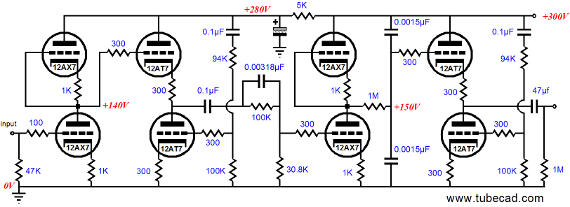
Hm, so what are we seeing, here? Four sequential stages, all directly-coupled.. alternating common-cathode (with active plate load) and cathode-follower (with active CCS). Only two stages, both 12AX7, have gain, whereas the 12AT7 stages are slightly less than unity. Am I interpreting that correctly?
Very nice to see 12AT7 in use driving the EQ network and the output - it's a generally underappreciated and under-used** tube.
(** With the exception of designs like Atma-Sphere, which uses like 8-10x 12AT7 in the MP-1 or 7x in the MP-3)
First off, notice that R03 (awful and confusing naming for a 12AX7 section!)
Not so confusing when the person is making the schematic for swedish speakers. I don't know the term they use for tube there, but it's probably similar to german "Röhre".
Hm, so what are we seeing, here? Four sequential stages, all directly-coupled.. alternating common-cathode (with active plate load) and cathode-follower (with active CCS). Only two stages, both 12AX7, have gain, whereas the 12AT7 stages are slightly less than unity. Am I interpreting that correctly?
Very nice to see 12AT7 in use driving the EQ network and the output - it's a generally underappreciated and under-used** tube.
(** With the exception of designs like Atma-Sphere, which uses like 8-10x 12AT7 in the MP-1 or 7x in the MP-3)
Correct. The neat thing about the way that the Aikido scheme works, is that using a triode as a CCS gives you complementary nonlinearity, which in theory (and from the low measured THD!) gives you a pretty simple circuit all things considered. The overall gain of each stage is 1/2 the mu of the tubes used. this is a nice circuit, because it amplifies the incoming signal, uses the cathode follower to give a low output impedance, applies the RIAA stage to the signal, then amplifies it again, with another cathode follower for output. The noise cancelling network at the grid of the cathode followers lower tube injects opposite phase PSU noise to cancel out some of the ripple and hash very well.
Is it perfect? No, not at all, but it makes a very good account of itself, and does so without any solid state devices of any sort, which is a big deal for some tube guys. just add the tube rectifier of your preference, and build it up.
If it was me, I would do something similar, but use a D3A or similar pentode, triode connected, CCS loaded, direct coupled to a Mosfet source follower that is also CCS loaded. Cascade this into the RIAA network, and then run a cathode follower output with a DC servo for direct-coupled output. Run the whole thing off of either a Maida regulator, or a shunt supply. Should be a pretty good circuit. Or, if you want all the design work and values already worked out, build Sy's phono stage- "His masters noise" and stop worrying

so getting back to the circuit in which I am most interested at the moment, can anyone comment on how critical the values of the stage coupling caps are? (5µF + 4.7nF) I'm wondering what happens to the RIAA eq if I change that. They seem like major overkill, and that even if I got with a large value like 5µF, the parallel capacitor is maybe not so important if film caps are used.
If I am correct in assuming that 1M resistors R8, R15, and R28 are to set the input resistance to the following stage, even using a .08µF coupling capacitor gives me flat response to 20HZ, with -3dp at 2HZ according to this calculator that I was using:
https://www.v-cap.com/coupling-capacitor-calculator.php
Using 1µF, that calculator gives me flat response down to 1.59HZ, and a -3dB point of 0.16HZ, which seems more than plenty for an audio frequency amp.
Any thoughts from folks who know better than I do about this?
Correct. The neat thing about the way that the Aikido scheme works, is that using a triode as a CCS gives you complementary nonlinearity, which in theory (and from the low measured THD!) gives you a pretty simple circuit all things considered. The overall gain of each stage is 1/2 the mu of the tubes used. this is a nice circuit, because it amplifies the incoming signal, uses the cathode follower to give a low output impedance, applies the RIAA stage to the signal, then amplifies it again, with another cathode follower for output. The noise cancelling network at the grid of the cathode followers lower tube injects opposite phase PSU noise to cancel out some of the ripple and hash very well.
Is it perfect? No, not at all, but it makes a very good account of itself, and does so without any solid state devices of any sort, which is a big deal for some tube guys. just add the tube rectifier of your preference, and build it up.
If the simple three tube thing doesn't cut the mustard for me, I'll be giving this aikido thing a try next! Just need to figure out where to slip the volume control and inputs for line level sources. I'll never have a MC phono cartridge, so only need phono amplification for "standard" MM type (currently a run of the mill, but plenty good enough for me stanton 680EE)
so getting back to the circuit in which I am most interested at the moment, can anyone comment on how critical the values of the stage coupling caps are? (5µF + 4.7nF) I'm wondering what happens to the RIAA eq if I change that. They seem like major overkill, and that even if I got with a large value like 5µF, the parallel capacitor is maybe not so important if film caps are used.
If I am correct in assuming that 1M resistors R8, R15, and R28 are to set the input resistance to the following stage, even using a .08µF coupling capacitor gives me flat response to 20HZ, with -3dp at 2HZ according to this calculator that I was using:
https://www.v-cap.com/coupling-capacitor-calculator.php
Using 1µF, that calculator gives me flat response down to 1.59HZ, and a -3dB point of 0.16HZ, which seems more than plenty for an audio frequency amp.
Any thoughts from folks who know better than I do about this?
I wouldn't bother bypassing the big film caps with smaller caps, a straight 5uF will be fine. Generally you only bypass a film across a big honkin' electrolytic capacitor, and even that is a matter of personal taste and principle.
R17 and R18 are only 10k, hence the big 5uF film caps. If you are leaving those particular outputs off you would be fine with a smaller cap for sure. R28 will be in parallel with the input resistor of whatever you plug this into, so that resistor could end up as low as 1M in parallel with a 10K volume control or such thing, so it might be a good idea to leave that one 5uF, unless you are certain your following stages are high impedance at the inputs...
Last edited:
thanks! my tape recorders of various vintages all seem to have a 47K - 50K input impedance. would I want to change those 10K resistors (r17/r18) to match?
My plan is to use this to drive a tube power amp that I'm slowly working on. I haven't made up my mind on the input resistors of that amp, but was thinking somewhere in the 250K-500K range. I've got most parts for a relatively simple (and hopefully satisfactory) 6bq5 PP stereo amp, and am working out the kinks in the design of a set of monoblocks using 6080/6as7. I suppose it would probably be smart to leave those 5µF caps in the output so that I can drive most anything I might come across.
I really appreciate all the help from everyone, (even those that side track me with other designs), as it is helping me really understand what everything is doing. I've been playing with this stuff for many years, but because I'm mostly self taught, there are quite a few gaping holes in my education that are slowly getting filled in.
Now I've just got to find the piece of phenolic board that I was going to build this on, order a few parts, and hopefully then I'm off to the races.
what purpose do r17/r18 serve in the circuit? is it to help balance/isolate the load between the tape deck(s) and the line stage that follow it? What happens if they are not there at all? is the load seen by the output of the phono stage then determined by the 1M resistor (R15) paralleled with the balance and volume pots?
Hello anchorman,
Yes, that is right.
You are of course correct that 'R' indicates röhre. The main confusion is direct conflict with the common use of R for resistor. Both were equally correct at the time, but today it's a source of confusion for some (like me, lol).
Not so confusing when the person is making the schematic for swedish speakers. I don't know the term they use for tube there, but it's probably similar to german "Röhre".
Yes, that is right.
You are of course correct that 'R' indicates röhre. The main confusion is direct conflict with the common use of R for resistor. Both were equally correct at the time, but today it's a source of confusion for some (like me, lol).
I am new to the 2R2 type nomenclature, but I've grown to like it.
I'm guessing they use(d) either use Ω w for resistance? The worst thing for me is the way that non-Americans lay out the circuits in the diagrams. Some folks do it so differently that it feels like learning a foreign language, but worse.
I'm guessing they use(d) either use Ω w for resistance? The worst thing for me is the way that non-Americans lay out the circuits in the diagrams. Some folks do it so differently that it feels like learning a foreign language, but worse.
Hello anchorman,
Yes, that is right.
You are of course correct that 'R' indicates röhre. The main confusion is direct conflict with the common use of R for resistor. Both were equally correct at the time, but today it's a source of confusion for some (like me, lol).
In fact, in the schematic it says RO1, not R01. But still, for many years it has been uncommon not to use an international designation (like e.g. V instead of RO), even when the schematic is expected to be read only by a domestic public.
In fact, in the schematic it says RO1, not R01
Very good of you! I for one failed to note the R0 vs RO distinction.
On the Dutch side we use a "B" (Buis) for the tubes.You find that in old service manuals from Philips.
For resistors (and others) we write 2k2 for 2,2kΩ or 4µ7 for 4,7µF.
A problem with 2,2Ω.You see 2R2 but using the "R" is confusing with names R5 R6 R7.I write 2E2 for "Eenheid" (unity in Dutch).
In europe we use the "," for decimals not "." more reliable, some times you can see dot and take it for a point (or miss the point ).Much less risk with a comma.
And what about µµF in place of pF or 20000µF for 20mF
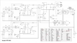
Back on the subject, here is the Japanese pre- (Sharp) after I turned it upside down to get rid of some of those eastern fantasy.
Mona
For resistors (and others) we write 2k2 for 2,2kΩ or 4µ7 for 4,7µF.
A problem with 2,2Ω.You see 2R2 but using the "R" is confusing with names R5 R6 R7.I write 2E2 for "Eenheid" (unity in Dutch).
In europe we use the "," for decimals not "." more reliable, some times you can see dot and take it for a point (or miss the point
).Much less risk with a comma. And what about µµF in place of pF or 20000µF for 20mF
Back on the subject, here is the Japanese pre- (Sharp) after I turned it upside down to get rid of some of those eastern fantasy.
Mona
Attachments
what purpose do r17/r18 serve in the circuit? is it to help balance/isolate the load between the tape deck(s) and the line stage that follow it?
R17 / R18 set an up-front resistive Zin for the line section. You are correct that without these parts, any input signal would be left to driving the volume / balance network. Any modern source should be fine with 10K Zin, and likewise the output of the RIAA phono amp, with the ~5u output coupling cap.
What happens if they are not there at all?
In many cases, probably nothing audible. But then there's that whole thing about transmission lines with matched source and load impedances.. Figure that so much consumer audio gear seems to get along so well, without much end-user thought on what might be going on with (un)matched impedances.
- Status
- This old topic is closed. If you want to reopen this topic, contact a moderator using the "Report Post" button.
- Home
- Amplifiers
- Tubes / Valves
- want to build all tube preamp