Hi all
As my circuit analysis is quite disastrous, I went to Morgan Jones "Valve Amplifiers fourth edition"
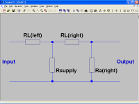
He makes an analysis with two potential dividers

And he arrives at
Crosstalk = 20 Log {[Rsupply / (Rsupply+RL)] [Ra / (Ra+RL)]}
For a stereo pair of common cathode E88CC stages
RL=33KΩ Ra=6.6KΩ Rsupply=2Ω
Crosstalk = -100dB
For two SRPP stereo stages, my books burned out, my guess is
RL≈10mΩ (Cable) Ra≈5.2KΩ Rsupply≈10mΩ (Shunt Regulator)
Crosstalk ≈ -6dB
This result is disappointing, did I miss something?
As my circuit analysis is quite disastrous, I went to Morgan Jones "Valve Amplifiers fourth edition"
He makes an analysis with two potential dividers
And he arrives at
Crosstalk = 20 Log {[Rsupply / (Rsupply+RL)] [Ra / (Ra+RL)]}
For a stereo pair of common cathode E88CC stages
RL=33KΩ Ra=6.6KΩ Rsupply=2Ω
Crosstalk = -100dB
For two SRPP stereo stages, my books burned out, my guess is
RL≈10mΩ (Cable) Ra≈5.2KΩ Rsupply≈10mΩ (Shunt Regulator)
Crosstalk ≈ -6dB
This result is disappointing, did I miss something?
Attachments
RL is the load resistance of whatever you are driving, and as the previous poster pointed out it's not the dcr of the cable.
The equations are intended for a resistively loaded amplifier stage. RL in this case would be the equivalent resistance of the upper device in the SRPP which you might liken to a mediocre CCS. Figure out how good a CCS the upper triode is and you can determine the cross talk.
The equations are intended for a resistively loaded amplifier stage. RL in this case would be the equivalent resistance of the upper device in the SRPP which you might liken to a mediocre CCS. Figure out how good a CCS the upper triode is and you can determine the cross talk.
RL is the load resistance of whatever you are driving, and as the previous poster pointed out it's not the dcr of the cable.
The equations are intended for a resistively loaded amplifier stage. RL in this case would be the equivalent resistance of the upper device in the SRPP which you might liken to a mediocre CCS. Figure out how good a CCS the upper triode is and you can determine the cross talk.
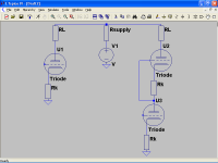
Hi Kevin, thank you very much, you may refer to something like this
I will redraw to understand a little bit better.
Attachments
Yes, except in this case you would use rp (ra) of U2 for the calculation in the SRPP rather than external RL you've added which for the SRPP case may be ignored.
The RL Morgan Jones is referring to is just the plate load resistor in a simple common cathode amplifier and ignoring any external load.
The RL Morgan Jones is referring to is just the plate load resistor in a simple common cathode amplifier and ignoring any external load.
U2 = RL in this scenario, there is no separate RL
You need to determine the value of rp at the plate of U2, this value replaces RL.
Yes Rl is the load resistance. And wouldn't the tube internal impedance be ra rather than Ra? Ra would be what is marked as "RL" in the screen cap of the Spice simulation; e.g. "plate load" resistors?
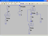
I think that I got it, roughly
Crosstalk = 20 Log {[Rsupply / (Rsupply+Ra)] [RL / (Ra+RL)]}
Edit: It should be RL=Ra assuming an infinite load, right?
Last edited:
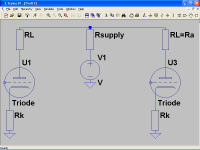
Crosstalk = 20 Log {[Rsupply / (Rsupply+Rp)] [rp / (rp+Rp)]}
Rp=plate load
rp=tube impedance
Me thinks.....
We both post at almost the same time, finally
Crosstalk = 20 Log [Rsupply / 2(Rsupply+Ra)]
Thanks again.
Please accept my apologies, I was so excited with the figures obtained that I lost some details, but I have a good alibi. 
Just to follow my own notation I did ra=Ra, I know that it is not the proper notation but I went a little dizzy with rp, Rp, and so on, anyway both triodes are supposed equals and ra of upper triode is Ra for the bottom triode, or whatever.
BTW, my shunt regulator has less than 1mΩ of output impedance, from 10Hz to 100KHz, at least in simulations, so crosstalk figures would be even better.
> my shunt regulator has less than 1mΩ
Then if the thing sending crap to it has at-least 33K in it, the rail is at 0.001/33K or "huge", -150dB.
The stage getting rail crap may have 6dB-10dB PSRR, a bonus hardly worth counting.
FWIW: resistance of #20 Copper is about 10mOhm/foot, so it will need thoughtful layout to get milli-Ohm-ish rail *and ground* impedances.
FWIW: resistance of #20 Copper is about 10mOhm/foot, so it will need thoughtful layout to get milli-Ohm-ish rail *and ground* impedances.
Or put the boards very close each other; how that close? With your wire, about 1.5cm.
Stupid question: #20 is the thickest wire over there?
Liquid air is cheap, so superconductivity is another option...damn, valves will not be very happy, they hate liquid air.
Almost forgot the layout, I have some 6mmx4mm copper wire to reduce track resistance, once I did obtain good results that way, seriously.
I take the opportunity to ask you an indiscreet question, you joined the forum on 2003, in all those years you could not learn to use the quote button?
No offence intended, just curiosity.
Last edited:
- Status
- This old topic is closed. If you want to reopen this topic, contact a moderator using the "Report Post" button.
- Home
- Amplifiers
- Tubes / Valves
- Help needed in Crosstalk calculation