Just thought I would drop by and get a sanity check for my current build. For the first time ever, I've decided to actually build a maida regulator, and use a CCS plate load on one of my builds. I prefer the concertina for my phase splitters at such levels (and they are by nature extremely low distortion topologies that exhibit excellent balance) so here it gets one too.
Design goals-
10~15 watts output
Reasonably low THD
Pentode mode, with adjustable screen supply
Great overload/blocking prevention and recovery
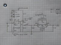
Input stage is a 6sl7 grounded cathode with a red LED for bias, and CCS plate load. Concertina phase splitter is connected with a capacitor-shorted resistor divider, as seen in Sy's imPasse preamplifier. Pretty simple so far. I've used the same setup (resistor loaded to drive 70v p-p into the grids of my parallel push pull 6as7g project (loaded with a resistor, even, instead of CCS) with great results. I might lower the load resistors from 100k to 68k, to get a bit more current though the concertina. A 12at7 or 6n2p, or even the lowly 12ax7 would work in this application I suppose, but I'm keeping it octal.
I already have a 150VA Toroid that makes 350 volts rectified, and has two 6.3v windings. It is an old isolation transformer that I added several windings to, and wired one of them in series for extra voltage. I've used it in another amplifier for a couple years without any issues. That takes care of my B+ supply. I will most likely do some basic RC filtering on the input and phase splitter stage, since it is pretty trivial do do well. Solid state rectified, no chokes.
The screen supply will get the version of the Maida regulator that Sy used in the Red light district amplifier. Pretty straightforward solution there.
The 6v6 Output stage gets an 8k load, and will be cathode biased with a capacitor/resistor for now, and an LED array once I get the output stage set up how I like it. From past experiences at 350v plate the 6v6 likes anywhere from 20~24v of bias, and around 265v screens. My main question is the grid stopper. Will 47k work here like on the EL84 RLD amplifier? Also, I should use the fixed bias grid leak value if I'm not mistaken, this should be a 100k resistor for the 6v6 from what the datasheets all say.
I might experiment with some sort of other biasing schemes, my chassis is repurposed from an older amp so it is pretty big and roomy for other boards and circuits to be added later on. The one that calls to me the most is of course a big fat glowing LED array though
Any suggestions? It's sort of a salad bar approach of ideas that I know work well, but will end up pretty much an all-octal Red light district in practice. Just with a few fancy features I guess
I've uploaded a schematic that should help, just let me apologize in advance for my handwriting!
Design goals-
10~15 watts output
Reasonably low THD
Pentode mode, with adjustable screen supply
Great overload/blocking prevention and recovery
Input stage is a 6sl7 grounded cathode with a red LED for bias, and CCS plate load. Concertina phase splitter is connected with a capacitor-shorted resistor divider, as seen in Sy's imPasse preamplifier. Pretty simple so far. I've used the same setup (resistor loaded to drive 70v p-p into the grids of my parallel push pull 6as7g project (loaded with a resistor, even, instead of CCS) with great results. I might lower the load resistors from 100k to 68k, to get a bit more current though the concertina. A 12at7 or 6n2p, or even the lowly 12ax7 would work in this application I suppose, but I'm keeping it octal.
I already have a 150VA Toroid that makes 350 volts rectified, and has two 6.3v windings. It is an old isolation transformer that I added several windings to, and wired one of them in series for extra voltage. I've used it in another amplifier for a couple years without any issues. That takes care of my B+ supply. I will most likely do some basic RC filtering on the input and phase splitter stage, since it is pretty trivial do do well. Solid state rectified, no chokes.
The screen supply will get the version of the Maida regulator that Sy used in the Red light district amplifier. Pretty straightforward solution there.
The 6v6 Output stage gets an 8k load, and will be cathode biased with a capacitor/resistor for now, and an LED array once I get the output stage set up how I like it. From past experiences at 350v plate the 6v6 likes anywhere from 20~24v of bias, and around 265v screens. My main question is the grid stopper. Will 47k work here like on the EL84 RLD amplifier? Also, I should use the fixed bias grid leak value if I'm not mistaken, this should be a 100k resistor for the 6v6 from what the datasheets all say.
I might experiment with some sort of other biasing schemes, my chassis is repurposed from an older amp so it is pretty big and roomy for other boards and circuits to be added later on. The one that calls to me the most is of course a big fat glowing LED array though
Any suggestions? It's sort of a salad bar approach of ideas that I know work well, but will end up pretty much an all-octal Red light district in practice. Just with a few fancy features I guess
I've uploaded a schematic that should help, just let me apologize in advance for my handwriting!
Attachments
Last edited:
There's a bunch of stuff in here that I'm not at all familiar with, so I'll reserve comment for now. But one thing I do question, is the use of 100nf caps -> 100K grid resistors on the 6V6s. Those tubes should be fine with 330K-499K (or even 1M, perhaps..) so why are you squelching so much low-end with these low resistor values?
The 100nF (0.10uF) are fine, so long as you keep the load resistors in the 300-500K range. As it is, you're blowing off a lot of low-end. But that might be intentional, so.. there you go.

Here's a detail from a typical vintage EL84 amp - close enough to 6V6 that it shouldn't make much difference. You can see that they're using 470K on the grids, with 47nF (0.047uF) parts, which is typical for the era (on the small side). Point being, you can use much higher grid resistors while still keeping the cap values lower - and that's a good thing.
The 100nF (0.10uF) are fine, so long as you keep the load resistors in the 300-500K range. As it is, you're blowing off a lot of low-end. But that might be intentional, so.. there you go.
Here's a detail from a typical vintage EL84 amp - close enough to 6V6 that it shouldn't make much difference. You can see that they're using 470K on the grids, with 47nF (0.047uF) parts, which is typical for the era (on the small side). Point being, you can use much higher grid resistors while still keeping the cap values lower - and that's a good thing.
Last edited:
There's a bunch of stuff in here that I'm not at all familiar with, so I'll reserve comment for now. But one thing I do question, is the use of 100nf caps -> 100K grid resistors on the 6V6s. Those tubes should be fine with 330K-499K (or even 1M, perhaps..) so why are you squelching so much low-end with these low resistor values?
The 100nF (0.10uF) are fine, so long as you keep the load resistors in the 300-500K range. As it is, you're blowing off a lot of low-end. But that might be intentional, so.. there you go.
I might go up in value on the caps, but since this amp will behave more like a fixed bias amp (and this is discussed in the original Red light district amplifier article) it needs the smaller value grid resistor since there is no cathode resistor to give any sort of cathode current feedback at the 6v6. I'm ok with a 100n/100k though, as it gives a -3db point of 15.92Hz. Not what I would necessarily consider a ton of low end being thrown away. I usually use 100n/1M but wanted to play it safe here. I see the guitar guys frequently use larger values than the datasheets recommend for fixed bias operation, but there are a lot of bending the rules in guitar. If Sy or someone else with more engineering background than me drops in and gives me the go ahead I'll swap the 100k for something bigger, many other tubes get a bigger resistor in the datasheets, so I'm not certain why the 6v6 restricts you to 100k in fixed bias... I'm using the Russian 6P6S (6v6) tubes if that matters, but they bias up exactly like all the other 6v6 I've used
I might go up in value on the caps, but since this amp will behave more like a fixed bias amp (and this is discussed in the original Red light district amplifier article) it needs the smaller value grid resistor since there is no cathode resistor to give any sort of cathode current feedback at the 6v6
I see.. so there's (really important) stuff you're not showing in the 'cathode load' box. I took this to be a simple resistance, with or without bypass, to be selected as needed. So if your bias system effectively acts like a fixed negative grid supply (C-), then you are correct that the grid resistances need to be lower than in the case of a cathode-bias setup.
it gives a -3db point of 15.92Hz. Not what I would necessarily consider a ton of low end being thrown away.
And I'm used to setting that -3dB cutoff at 0.5Hz - 2Hz. But that's in another universe..
Again, it's a weird one to me, but I'm way out of the loop on this kind of thing. By all means, build it up and share what you find - this is how we thrive!
Last edited:
Again, it's a weird one to me, but I'm way out of the loop on this kind of thing. By all means, build it up and share what you find!
I've got the chassis half wired so far, and I'm waiting on some parts for the CCS plate loads, so not too much I can do in the meantime. I'll build up a screen regulator in the next couple days to set my operating point for the output tubes.
Here's the original Red light district article, if you'd like a nice design to read through. It goes into detail on some of the reasoning, and the LED array that will be used as a cathode load. The article for the imPasse preamp is on his site too-
The Red Light District: A 15W Push-Pull Amplifier
I like the resistor divider between the 2 halves of the 6SL7, it keeps the cathode of the second half to a lower DC level (Cathode to filament voltage rating, and the leakage thereof).
Consider 105k total grid resistance (100k grid resistor to ground plus 5k grid stopper resistor).
Then if the 6V6 has 10 uA of grid leakage current, that is 1.05V.
The 6V6 transconductance is about 3700 uMhos.
So, with LEDs in the cathodes (a kind of fixed bias), 1.05 V more bias means 3.7 mA more current will flow.
When more current flows, the tube gets hotter, and the grid current goes up even more ... and you might get thermal runaway.
I was a little surprised that the grid resistor spec is only 100k, but perhaps the 6V6 has more grid current than I suspected (perhaps because some designers choose to use the tube at the maximum plate and screen dissipation).
I recently constructed something very similar, with the same things borrowed from Sy's Red Light District. CCS load, red LED cathode bias, even the same 47 ohm cathode resistor for the feedback connection. I started out with the 47k grid stoppers into the finals but they caused some high frequency instability with the feedback connected (~20 dB feedback, so more than in Sy's design) and I ended up with the standard 1k. I'm very happy with the result.
I recently constructed something very similar, with the same things borrowed from Sy's Red Light District. CCS load, red LED cathode bias, even the same 47 ohm cathode resistor for the feedback connection. I started out with the 47k grid stoppers into the finals but they caused some high frequency instability with the feedback connected (~20 dB feedback, so more than in Sy's design) and I ended up with the standard 1k. I'm very happy with the result.
Cool! What b+ did you use for your outputs? Any idea how many LED (and voltage of the LEDs) per string it took?
Got a thread or schematic for how you implemented everything?
Cool! What b+ did you use for your outputs? Any idea how many LED (and voltage of the LEDs) per string it took?
Got a thread or schematic for how you implemented everything?
Sorry, the front end was inspired by the Impasse and RLD, but the output stage was fixed bias, no LEDs there. I used the RLD Maida regulator for the screens, one for each channel. Output stage is 7591's, ~400V anode, 350V screen and 38mA per tube. CCS used cascoded DN2540's because I already had them constructed on perfboard from a previous use in a LTP tail. Current was adjustable, and I could use it to tweak the anode voltage as phase splitter was direct coupled and thus more sensitive to first stage operating point.
As Wavebourne said, you will likely need some compensation networks for feedback stability. I ended up with the usual capacitor in parallel with the feedback resistor, and an RC network from first stage anode to ground. I also had zobels across each half of the output primary but could probably have done without them. Lots of playing around with square waves and a scope to get the right values.
I did a quick simulation. I haven't checked the accuracy of the models I used but the following seems to be a good starting point:
First stage 1.2mA current, 190V anode, 1.6V cathode.
Phase splitter 68k load resistors results in about 1.4mA. Dropping them lower increased distortion.
Front end B+ 320 volts.
Output stage 350V B+, 20V cathode, 60mA through LED array (120mA peak), 300V screen. 12W output allowing for transformer losses.
470 ohm feedback resistor for 8 ohm secondary, input 1.1V RMS for full output power.
LED array depends strongly on the LEDs you have. I tested a few different red LEDs and there was quite a difference in forward voltage drop. You would probably need around 8 parallel strings of 10 (or more) LEDs per channel. There's a reason that Sy used EL84s...
For the LED on the first stage cathode it might be in the non linear region with such a low current. You can run a resistor from B+ to the LED to increase current if necessary.
I did a quick simulation. I haven't checked the accuracy of the models I used but the following seems to be a good starting point:
First stage 1.2mA current, 190V anode, 1.6V cathode.
Phase splitter 68k load resistors results in about 1.4mA. Dropping them lower increased distortion.
Front end B+ 320 volts.
Output stage 350V B+, 20V cathode, 60mA through LED array (120mA peak), 300V screen. 12W output allowing for transformer losses.
470 ohm feedback resistor for 8 ohm secondary, input 1.1V RMS for full output power.
LED array depends strongly on the LEDs you have. I tested a few different red LEDs and there was quite a difference in forward voltage drop. You would probably need around 8 parallel strings of 10 (or more) LEDs per channel. There's a reason that Sy used EL84s...
For the LED on the first stage cathode it might be in the non linear region with such a low current. You can run a resistor from B+ to the LED to increase current if necessary.
Neat. I need to dig through all my multchip LED arrays and see if i have something that will work at my needed voltage. I have some that sit around 11v that might work in series for about 22v at the cathode- with a 350v plate supply and adjustable screens that might just put me in the ballpark.
Idea that just popped into my head- I could return the resistor from my CCS to ground to the cathode of my input stage, this would feed around 5mA from the reference string into the bias LED, and only raise the bias by around .28v due to the added current through the 47R feedback resistor. No more difficult to arrange either. Two birds, one stone
Would keeping the concertina loads at 100k be a good ide, or should I go to 68k? It seems either would be good linearity wise, but I like the idea of runing a bit more current through the triode, especially with 100k grid resistors at the output grids.
Idea to keep in mind- at such low currents, it seems that a shunt regulator would be an interesting filter solution for the input/PI stage, but we might play with that more later, since other than gas VR tubes, I have no experience there...
Looks good. Shoot for flat closed loop frequency response out to 30KHz or even 35KHz if you can (depends on output transformers though). 100 to 150 ohm screen stopper resistors on the 6V6's should be fine.
Is the CT feed also regulated? If not, rather than a full-blown Maida, you might get by just as well with a simpler screen supply consisting of a single mosfet, where gate voltage is resistor divided down from the B+ supply.
Is the CT feed also regulated? If not, rather than a full-blown Maida, you might get by just as well with a simpler screen supply consisting of a single mosfet, where gate voltage is resistor divided down from the B+ supply.
- Status
- This old topic is closed. If you want to reopen this topic, contact a moderator using the "Report Post" button.
- Home
- Amplifiers
- Tubes / Valves
- A push-pull 6v6 amplifier design for your approval, not for the purists!