You will want to specify AC current, as saying 200mA of DC current won't indicate the load on the transformer without providing the electrical design and working backwards.
So "640V CT 300mA with a bias tap at 60V" would be what I would ask for.
Thanks
")
The amp discussed in this thread is a monoblock derivative of the amp posted here, a mild mannered 18 WPC design using TV sweep (line output) tubes.
I bought one of Petes "big red boards" stating that I would be disappointed if I didn't get at least 50 WPC. That barrier was broken the first day I put power to the board. The most I saw from "big red" was 250 Watts Per Channel, or 525 watts mono from both channels in parallel through a single large OPT.
I then backed the power down to 125 WPC and posted the mods for anyone to copy. I know of at least 10 that were done. Pete did a version of this board for the same 6HJ5 tubes that I used for 125 WPC, and another version with no output tube socket at all so nearly any tube could be used. I have never seen either of these boards, but the design is similar, so plenty of power is available.
The entire long thread is worthwhile reading for a technically minded person. The high power experiments start in post #218.
The 6HJ5 first met the board in post #232. 250 watts @3%THD happens in post #425 and 504 watts mono in post# 438.
Somewhere after that the concept of a split power supply using two transformers was used. The board itself only sees 350 to 400 volts, and thus no high voltage caps are needed. A second power supply is stacked on top of that for power to the output tube plates only.
The amp discussed in this thread is a monoblock derivative of the amp posted here, a mild mannered 18 WPC design using TV sweep (line output) tubes.
I bought one of Petes "big red boards" stating that I would be disappointed if I didn't get at least 50 WPC. That barrier was broken the first day I put power to the board. The most I saw from "big red" was 250 Watts Per Channel, or 525 watts mono from both channels in parallel through a single large OPT.
I then backed the power down to 125 WPC and posted the mods for anyone to copy. I know of at least 10 that were done. Pete did a version of this board for the same 6HJ5 tubes that I used for 125 WPC, and another version with no output tube socket at all so nearly any tube could be used. I have never seen either of these boards, but the design is similar, so plenty of power is available.
The entire long thread is worthwhile reading for a technically minded person. The high power experiments start in post #218.
The 6HJ5 first met the board in post #232. 250 watts @3%THD happens in post #425 and 504 watts mono in post# 438.
Somewhere after that the concept of a split power supply using two transformers was used. The board itself only sees 350 to 400 volts, and thus no high voltage caps are needed. A second power supply is stacked on top of that for power to the output tube plates only.
Thank you!
just since i can't wait... for 150W and above, does the design remain the same? One driver stage, one power stage? Thanks
Last edited:
All of my experiments were done on the original two channel board. No changes to the design were made, but component value tweaks took place to optimize things for the power and voltage levels in play at the time.
Obviously more gain is needed to get 250 WPC than 18 WPC, so the driver tube was changed to a 6GU5 which has more Gm than the original 6CB6, and the plate load and feedback resistors were tweaked to boost the gain. I never measured the input sensitivity at 250 WPC, but I could drive the 125 WPC version to clipping with my CD player.
One thing to remember is that the plate voltage on the output tubes will reach 2 X the B+ voltage on signal peaks under normal HiFi operation into a resistive load. It can reach 4 X B+ in a guitar amp driven to clipping into a real speaker load near it's resonant frequency.
The traces on the PC board connecting the output tube plates to the feedback resistors in the original two channel amp ran too close to other low level traces for long term continuous operation at 250 WPC. I used one of my 125 WPC versions for PA duty at a couple of outdoor rock concerts without incident, but the amp was not driven to clipping.
I have not seen any of the PC boards for Pete's later monoblock versions, So I can't comment on the layout. The feedback resistors will see voltages well in excess of 1KV, so they should be rated for HV use, or multiple resistors in series should be used. Keep them far from other parts and traces. I had a resistor arc to a ground trace in one of my own boards and it blew a hole in the PCB.
All of my experiments were done on the original two channel board. No changes to the design were made, but component value tweaks took place to optimize things for the power and voltage levels in play at the time.
Obviously more gain is needed to get 250 WPC than 18 WPC, so the driver tube was changed to a 6GU5 which has more Gm than the original 6CB6, and the plate load and feedback resistors were tweaked to boost the gain. I never measured the input sensitivity at 250 WPC, but I could drive the 125 WPC version to clipping with my CD player.
One thing to remember is that the plate voltage on the output tubes will reach 2 X the B+ voltage on signal peaks under normal HiFi operation into a resistive load. It can reach 4 X B+ in a guitar amp driven to clipping into a real speaker load near it's resonant frequency.
The traces on the PC board connecting the output tube plates to the feedback resistors in the original two channel amp ran too close to other low level traces for long term continuous operation at 250 WPC. I used one of my 125 WPC versions for PA duty at a couple of outdoor rock concerts without incident, but the amp was not driven to clipping.
I have not seen any of the PC boards for Pete's later monoblock versions, So I can't comment on the layout. The feedback resistors will see voltages well in excess of 1KV, so they should be rated for HV use, or multiple resistors in series should be used. Keep them far from other parts and traces. I had a resistor arc to a ground trace in one of my own boards and it blew a hole in the PCB.
Almighty God!
Well, thank you for explaining, I'll go through the entire thread, I've seen some pages, very interesting with the step tester...
I guess I don't need the 250wpc, around 100W would be more than enough even if I was living in a Renaissance castle....
And also the facts that some tubes you used are difficult to find here in Europe nor there is direct equivalents...
One point more, I arrived at page 26, and noted that you used a single chassis, did you try the two transformer version with two monoblocks?
Regarding dielectric arc... I don't know if it's the case to cable in the air (is it said so in English? Or better point-to-point?)
Thanks again,
Mike
I arrived at page 26
Page numbers on this forum are meaningless. The number of posts per page vary depending on your page size, screen resolution, and web browser. I have no idea which post you are referring to. Please reference things by post number.
I never built a monoblock version of this amp. I did run lots of bench tests on a bare board with bench power supplies, and several combinations of budget power transformers.
I built two stereo amps for myself, one using the "10 pound for $15" transformer to run the board and an Antek toroid for the plate boost supply. It used Edcor 100 watt 3300 ohm OPT's.
The other used two Anteks and some budget recycled OPT's, also 3300 ohm. It produced a bit less power due to a slightly lower B+ voltage.
Both were built on a single chassis and used 6GU5's and 6HJ5's.
Ok, just for info, the board(s) remain untouched, right? So that I can proceed straight to the order...
Stereo or better dual mono means two boards, then...
Thanks
.Both were built on a single chassis and used 6GU5's and 6HJ5's
Yes. I built two stereo amps using Pete's original large red board. Both used 6GU5's and 6HJ5's.
One amp used the "10 pounds of power for $15" surplus transformer mentioned in the thread to power the red board with about 310 volts. There was an Antek toroid (I don't remember the number) with its own bridge rectifier and filter cap to produce another 320 volts or so. This was wired in series with the board B+ to produce 630 volts for the output tube plates. This amp made 125 WPC at the edge of clipping with both channels driven. I used it off and on for 3 or 4 years, including some very loud outdoor music sessions. I gave that amp to my (former) boss when I retired in 2014.
The second amp never got a pretty chassis, it was stuffed in a wood box and used with a guitar preamp as a 200 watt guitar amp. The board was built as the same time as the amp described above, and used all the same parts and tubes. It got two Antek toroids for power and some smaller OPT's. I planned to make this into a killer guitar amp, hence the lighter weight transformers, The total B+ in this amp dropped to about 600 volts when both channels were driven, so it made about 110 WPC. As my 41 year engineering career was coning to an end, it got stuffed into a box somewhere when I had to move everything I owned twice for a total of 1200 miles. I have not seen it since the moves.
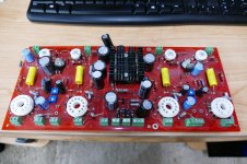
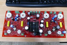
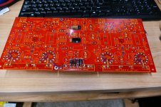
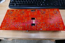
There was a third board, actually my first, that I got just for experiments. It is the board seen in all of the pictures. It was never built up into a complete amp.
Keep in mind that all of these experiments and amp building happened about 10 years ago. The cheap surplus power transformers are no longer available. 6HJ5's have become rather scarce. Some minor modifications to the board were needed to accommodate the 6HJ5's.
I found my original "experiment" board a couple years ago in a box full of old boards. I am enclosing pictures of it. The crossed over resistors near each output tube were needed to swap the G1 and G2 connections for the 6HJ5. I believe that the added diodes were to accommodate the cheap power transformer that needed a FWB rectifier. The board will draw too much current at full power for the small diodes in the parts list so larger (3 amp) diodes were used.
the board(s) remain untouched, right? So that I can proceed straight to the order...
I have never SEEN Pete's new boards, I do not know if any modifications will be needed. I do know that there are (or were) two versions, one that used the 6HJ5, and one with a hole in it so that any output tube could be used.
You said in your first post that you are an engineer. Approach this like an engineering problem. You want to make an amp of about 100 to 125 WPC, stereo, or dual mono. For this design, you will need two TV sweep (line output) tubes per channel that are rated for at least 24 watts of plate dissipation. More would be better. My experience says that a 3300 ohm OPT will get there on at least 600 volts of plate supply voltage. You could use a lower impedance (about 2500 ohms) OPT on a lower supply voltage (about 500 - 550 volts) , but going below 2500 ohms may run into peak current limitations in the output tubes. The first hurdle here is to find out what tubes and transformers are available in your part of the world. Once this is figured out, the best board for the job can be chosen. I have no idea which of Pete's boards are still available, since I have not built any of his stuff in nearly 10 years.
The original Engineers amp used 7 pin miniature tubes for the driver. They are not as common in your part of the world. There are lots more choices in the 9 pin size, but that would require a different board. Pete made a nice driver board that could use a long list of different high Gm tubes including the common 6EJ7. It would require wiring up your own output tube sockets.
I am relying on 10 year old memories, and an old beat up board from a box of "dead projects" here. I have not actually worked on these designs in over 8 years. I offer my guidance, but I have no idea as to what your actual experience level is when it comes to building big tube amps. I would recommend reading through anything you can find about this amp, and not proceeding until you understand how and why some of the decisions were made. Somewhere in that long thread you will find at least two plated where I blew parts in half, or clean off the board. 600+ volts is not something to play with if you are fully understanding what's going on. It can make a mess out of some expensive parts (or worse) in short order when things go wrong.
Attachments
yes, thank you again for your guidance...
is that I'm seeing now two red boards, one, smaller, for 2 power tubes, and another one, in your projects' refinement, bigger, for the two channels.
I'm an engineer, but electronics is a hobby, so I am still learning... Of course I eon't throw in 600V just like this, I'm just collecting info to see where I can get with other OPT, available tubes and so on...
OP and power transformer can be made to measure, but about circuital modifications I won't trust myself...
So reading the thread now, and see how it developed
.
Yes. I built two stereo amps using Pete's original large red board. Both used 6GU5's and 6HJ5's.
Hello, so, I'm going forth on the thread.
Since 6GU5 tubes are difficult to find in this part of the world, I guess I will use some other horizontal sweep tubes with a good dissipation factor for the output (and possibly with no cap, to get an higher WAF).
I just wanted to ask you, in the end, how is the calculation done for anodic resistance load and for OPT, and of course how this influences the plate voltage (and eventually power out) ?
I mean, when assembling (I don't have so many OPT at hand to do tests), how can I say whether I need a 2800R or 3300R or 5000R OPT ?
And how to pair the anodic load ?
And how much B+ voltage will do I need ?
Let's start from tube curves:
I get plate current, I try to get somehow cathode current. And then?
Let's say, I can build lego schemes, but modding a project is not yet for me, is smoething I'd like to learn tough
Since the time of the good old PL81 I can't remember any sweep tube here in Europe without plate top cap. And this is for good reason, I think.
Best regards!
Yes, i loked shortly on internet, then I'll go american
I'm wondering how the Americans managed to bring out a Compactron sweep tube's plate connection through the base without the risks of corona or even arcing.
Best regards!
Do you wonder about American technologic supremacy?
.....Since 6GU5 tubes are difficult to find in this part of the world, I guess I will use some other horizontal sweep tubes with a good dissipation factor for the output...
Mr. Millett is using 6GU5 tubes for the input/driver, not output. 6CB6's are much more common and should do fine for the input/driver.
Mr. Millett is using 6GU5 tubes for the input/driver, not output. 6CB6's are much more common and should do fine for the input/driver.
You're right, i meant the power output sweep pentodes 6hj5!
I'm wondering how the Americans managed to bring out a Compactron sweep tube's plate connection through the base without the risks of corona or even arcing.
Pins on either side of the plate pin are not connected. Raytheon states, "Do not use - It is suggested that socket clips for these pins be omitted to improve insulation factor of socket."
I would guess they feared designers using those two pins as 'tie points' for other circuitry and indeed getting arcing.
- Home
- Vendor's Bazaar
- 50W monoblock "Engineers Amp"