Hello Guys,
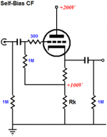
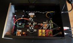
I just finished building a tube buffer using a cathode follower (6H30 tube). I have attached the schematic I used and also a picture of my tube buffer. I added a resistor of 56R between cathode and output cap.
The output caps are Wima MKP10 10uF 630V DC 400V AC. When powering on I do measure DC at the output on the 10 uF WIMA caps, it goes up as high as 55V and then slowly drops back to zero again in a total of about 90 seconds. This behaviour is exactly the same on both channels and the caps are brand new.
How is this possible, DC after the caps? Is this normal in tube amps?
Regards,
Ronald
Attachments
Last edited:
I believe what you are seeing is normal when using a rather large output cap into a very high load impedience. Try a smaller cap or a much lower load impedance . With a 1k load impedience instead of that 1m you are using the voltage should be back to 0 in about 1/10 of a second. You may want to read about what is called the R/C time constant.
I agree here.I believe what you are seeing is normal when using a rather large output cap into a very high load impedience. Try a smaller cap or a much lower load impedance . With a 1k load impedience instead of that 1m you are using the voltage should be back to 0 in about 1/10 of a second. You may want to read about what is called the R/C time constant.
Try 1uF and 100k as a more suitable design. Or even 0.47uF . It's no use
to transport subsonic energy to the next stage , it will only create possible problems.
Thanks guys,
I do know about RC time, just made a thinking error: how is it possible to have dc at output? But know I realize it actually is not DC but AC at very low frequency.
For now lowered resistor value (to test) and as you guys predicted this does solve the issue. Probably will replace caps too but glued them so thats why I took the easy way of replacing resistor first ;-)
Next stage has an input impedance of 10K. So if I use 5 Hz as -3 dB point then 1.5 uF instead of 10 uF would be fine. Maybe even a bit lower.
But why, in all examples I find , everyone uses such a high value resistor from output cap to ground?
Last edited:
Not everyone, I don't. Unjustified fear of loading down perhaps ? It is aThanks guys,
I do know about RC time, just made a thinking error: how is it possible to have dc at output? But know I realize it actually is not DC but AC at very low frequency.
For now lowered resistor value (to test) and as you guys predicted this does solve the issue. Probably will replace caps too but glued them so thats why I took the easy way of replacing resistor first ;-)
Next stage has an input impedance of 10K. So if I use 5 Hz as -3 dB point then 1.5 uF instead of 10 uF would be fine. Maybe even a bit lower.
But why, in all examples I find , everyone uses such a high value resistor from output cap to ground?
buffer, and as such it should be able to take some load.
And don't use 5hz as -3dB, use 20 hz if you have very good speakers, 30hz
otherwise. You don't want your bass elements to follow a warping record!
1. The tube cathode warms up slowly, then it gets to 100V (I took what was marked on the schematic, I did not calculate it).
This complicates the calculation of how the capacitor actually charges versus time, because of the tube warm up curve.
So, lets start from a Hot-Start. A hot-start is a worst case scenario, the power is on, and the circuit is warm and settled, then the power goes out, the B+ collapses to 0V, but the filament is still hot when the power comes back on.
2. The cap charges slowly, as it goes from 100V to 37V in 1 time constant.
3. By the fifth time constant, the output drops to 5V.
Why do people use such large output resistors?
Probably because they want to reduce the distortion of the cathode follower.
But then they often forget the actual load after the output connector.
i.e. 1 meg ohm and 10k, the load for all practical purposes is 10k.
Why do people use such large output capacitors.
Because they think bigger is better?
Because they saw somebody else do it?
The -3dB frequency point is one octave lower than the -1 dB point.
So, if you want 20 Hz at -1dB, design for -3dB @ 10 Hz (Xc = R load @ 10Hz).
Now, if you have 3 circuits in series that are -1 dB @ 10 Hz, the system is -3 dB @ 10Hz.
It stacks up quickly. i.e. power amp: driver stage cathode bypass cap - 1dB @ 10 Hz, RC cap driver to output tube grid -1dB @ 10 Hz, and Output transformer -1 dB @ 10 Hz, so the amplifier is -1, -1, -1dB = -3dB at 10Hz, which is ~ -1 dB @ 20Hz.
No one capacitor value will be optimal in everybody's system.
I do not have any 10k inputs. I do have some that are as low as 17k Ohms, but only when the volume control is turned all the way up, almost never is, (a remote volume control of 25k, that goes to a power amp input of 50k). I try and plan my coupling caps accordingly to the particular circuit they will be in.
Most of my setups are a CD player or a Tuner driving a 50k manual volume control directly.
And most of my setups only have 1 coupling cap, 2 cathode bypass caps, and an output transformer. If all poles are -1 dB @ frequency f, then the system is -4 dB @ f.
Because you don't want to load the valve more than you have to, you want a large cap to keep the output impedance low, and you want the -3dB frequency also to be low. And some people don't think hard enough about start-up conditions.But why, in all examples I find , everyone uses such a high value resistor from output cap to ground?
I use back-to-back 15V Zeners to clamp the voltage to safe levels.
Not everyone, I don't. Unjustified fear of loading down perhaps ? It is a
buffer, and as such it should be able to take some load.
And don't use 5hz as -3dB, use 20 hz if you have very good speakers, 30hz
otherwise. You don't want your bass elements to follow a warping record!
It's not that I want my speakers to output 5 Hz, but to avoid phase errors at the more realistic low frequencies (30 Hz and up) that my speakers will output, so that's why I took 5 Hz as an example to do my calculation.
1. The tube cathode warms up slowly, then it gets to
Why do people use such large output resistors?
Probably because they want to reduce the distortion of the cathode follower.
But then they often forget the actual load after the output connector.
i.e. 1 meg ohm and 10k, the load for all practical purposes is 10k.
Why do people use such large output capacitors.
Because they think bigger is better?
Because they saw somebody else do it?
The -3dB frequency point is one octave lower than the -1 dB point.
So, if you want 20 Hz at -1dB, design for -3dB @ 10 Hz (Xc = R load @ 10Hz).
Now, if you have 3 circuits in series that are -1 dB @ 10 Hz, the system is -3 dB @ 10Hz.
It stacks up quickly. i.e. power amp: driver stage cathode bypass cap - 1dB @ 10 Hz, RC cap driver to output tube grid -1dB @ 10 Hz, and Output transformer -1 dB @ 10 Hz, so the amplifier is -1, -1, -1dB = -3dB at 10Hz, which is ~ -1 dB @ 20Hz.
Actually I never even realized that bigger cap then needed would be an issue in some way, but now I do ;-)
I was mistaken about the input impedance of the next stage, it turns out to be 22k not 10k.
Thanks for your explanation and pointing out the effect of adding up all -3 dB points in the system!
- Status
- This old topic is closed. If you want to reopen this topic, contact a moderator using the "Report Post" button.
- Home
- Amplifiers
- Tubes / Valves
- 55V DC at output of CAP in cathode follower