Have you seen the 150x gain ? With 5mV from the cartrige the output is only ¾volts , what do you mean, lowering the gain ?
And on an output "minimum load 200000ohm".
Mona
You need to put a Cathode follower behind it i'v found out to get it right. I'm still puzzling how to do that.
I thought i needed someting like 64x (36dB) gain for a 5mV cartridge? this can easely be supplied with one 12ax7 triode side, so the second stage should be a cathode follower in my opinion, and at the end i need to find a way to adjust the volume with a pot after the cathode follower.
I know you have an allergic reaction to the idea of using the mosfet on the output, but you might want to do that first, get the circuit running, and then change it to the tube CF...
Anyway, here's some information about tube Cathode Followers -
The Valve Wizard -Cathode Follower
Brains & Brawn Cathode Follower
http://www.valvewizard.co.uk/dccf.html
http://www.diyaudio.com/forums/tubes-valves/59630-basic-cathode-follower-buffer.html
https://books.google.com/books?id=b...t#v=onepage&q=cathode follower buffer&f=false
Although the gain of a AX7 can be configured for that much, you are forgetting that the RIAA equalization costs about 30db, necessitating another gain stage after to get the signal back to where it started after the first tube section. This is why the 2nd tube section is configured for gain. The CF needs to be added after that.
Anyway, here's some information about tube Cathode Followers -
The Valve Wizard -Cathode Follower
Brains & Brawn Cathode Follower
http://www.valvewizard.co.uk/dccf.html
http://www.diyaudio.com/forums/tubes-valves/59630-basic-cathode-follower-buffer.html
https://books.google.com/books?id=b...t#v=onepage&q=cathode follower buffer&f=false
I thought i needed someting like 64x (36dB) gain for a 5mV cartridge? this can easely be supplied with one 12ax7 triode side, so the second stage should be a cathode follower in my opinion, and at the end i need to find a way to adjust the volume with a pot after the cathode follower.
Although the gain of a AX7 can be configured for that much, you are forgetting that the RIAA equalization costs about 30db, necessitating another gain stage after to get the signal back to where it started after the first tube section. This is why the 2nd tube section is configured for gain. The CF needs to be added after that.
Last edited:
You need to put a Cathode follower behind it i'v found out to get it right. I'm still puzzling how to do that.
I thought i needed someting like 64x (36dB) gain for a 5mV cartridge? this can easely be supplied with one 12ax7 triode side, so the second stage should be a cathode follower in my opinion, and at the end i need to find a way to adjust the volume with a pot after the cathode follower.
You've missed the fundamental point that the passive RIAA has a large insertion loss, you need the second triode gain stage. Walk before you run, build a proven design as designed and then modify to suit. Values in table below relative to 1kHz.
Attachments
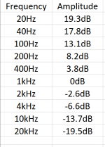
A "standard" CDP produces a max. 2 VRMS signal. The tweaked RCA setup yields approx. 45 dB. of gain. Apply that number to 5 mV. and you get 0.89 V. The peak O/P of a phono cart. is greater than 5 mV. So, if anything, you need a bit more than 45 dB. of gain in the RIAA preamp.
I know you have an allergic reaction to the idea of using the mosfet on the output, but you might want to do that first, get the circuit running, and then change it to the tube CF...
Anyway, here's some information about tube Cathode Followers -
The Valve Wizard -Cathode Follower
Brains & Brawn Cathode Follower
The Valve Wizard
http://www.diyaudio.com/forums/tubes-valves/59630-basic-cathode-follower-buffer.html
https://books.google.com/books?id=b...t#v=onepage&q=cathode follower buffer&f=false
Thank you for this info. The first i did knew, the rest not yet.
Although the gain of a AX7 can be configured for that much, you are forgetting that the RIAA equalization costs about 30db, necessitating another gain stage after to get the signal back to where it started after the first tube section. This is why the 2nd tube section is configured for gain. The CF needs to be added after that.
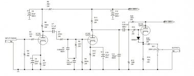
So you say the scheme should be something like this one (values still need to be recalculated in detail)
Attachments
Last edited:
Try this one, it sounds very good, easy to build too, just change C7=18nF to about 15nF to suit RIAA curve.
The article is in German, but it is easy to understand.
SRPP-Vorverstärker
It is a derivative of Anzai's SRPP, some people hate it, I do not know why.
The article is in German, but it is easy to understand.
SRPP-Vorverstärker
It is a derivative of Anzai's SRPP, some people hate it, I do not know why.
Yes. Build that.
If you want to recalculate anything, make the follower a 6DJ8 as Kevin suggested, it really does make a better CF than any of the 12A*7 series.
If you want to recalculate anything, make the follower a 6DJ8 as Kevin suggested, it really does make a better CF than any of the 12A*7 series.
So you say the scheme should be something like this one (values still need to be recalculated in detail)
It's no good.
Input impedance to high for a "normal" cartrige (can be taken care of)
High output impedance, only useful if inside a tube amp (short connection, low load)
For a RIAA correction if the high frequncies are amplified 1x the low side must have a gain of 100x. The max gain with a ECC83 is 100x without load and a CCS on the anode.So for a correct RIAA the second stage has to have a gain of less then 1x high frequency and max gain (=distortion) for the bas.
Between the two triodes is a useless 50Hz filter.
Mona
Not so fast, Mona -
Firstly the feedback factor for the RIAA stage is not known, but the gain is in the vicinity of x2 at 1 KHz. if one takes the feeding impedance of the first stage as approximately 70K. There is ample gain for the l.f. side of the RIAA; the second stage has a gain of <1 for the h.f. part. It is not my preferred topology, but no problem there regarding obtaining the necessary frequency compensation .
Then I am also puzzled by that twin-T filter, but it is not a normal balanced 50 Hz filter; notice the component values and associated components. I am unfortunately unable to access my Spice right now, thought it to be doing low cut-off rumble duties, but for that the values again look wrong. The author of the circuit gave no response graphs?
Not sure why a 100K resistor is included in series with the output. Without that the circuit would be quite able to drive a normal tube amplifier not connected through meters of proper cable.
In general:
The Quad RIAA stage is a simple pentode inverse anode-grid feedback setup with a 100K input resistor. In the circuit given it is 'swamped' by all the switching paraphenalia for other purposes - cumbersome to trace off the full schematic. The highish 100K input impedance might add some noise, but was the popular circuit of the day as said by Eli (was it?)
Then folks .....
do I need to return my varsity certificate? Why is everybody calling common shunt anode-grid feedback positive?? Yes, phase-shift wise there could be a phase turnover at h.f., easily swamped by a small resistance in series with the h.f. attenuating capacitor, if that is what was meant. Likely instability otherwise? Not that I have encountered after having done umpteen models with different component values - unless it is heroically misdesigned.
One can suggest any number of different circuits. Perhaps OT: My own preference is a twin triode (even a triode-pentode) with series feedback from the output anode to the input cathode. That could include RIAA equalising plus proportioning existing time constants so that a very useful >12 dB/octave low-cut feature can be had without any extra components. [Not to go into argumentative regions, but a useful low-cut circuit cutting rumble could be had for a few $ of components, that it might cost several $100 extra to obtain from a more expensive turntable. That apart from other advantages. (Signal components below say 25Hz has no business being amplified by a RIAA circuit - but that is another topic.)]
In addition such a topology should have a low enough output impedance to drive most power amplifiers. But as said, rather OT here - not to hi-jack.
Last edited:
Aha! Just found this -
RIAArca10ECC99
The phonostage is basically the RCA and it has a 6n6p follower. Still only needs a 230-250v supply. Very nice. I can read enough French to get an idea of the circuit description, but the schematic is clear. May I assume that living in Belgium your francais is better than mine!
RIAArca10ECC99
An externally hosted image should be here but it was not working when we last tested it.
The phonostage is basically the RCA and it has a 6n6p follower. Still only needs a 230-250v supply. Very nice. I can read enough French to get an idea of the circuit description, but the schematic is clear. May I assume that living in Belgium your francais is better than mine!
You should include a cap between the cathode followers cathode and the output.Thank you for this info. The first i did knew, the rest not yet.
So you say the scheme should be something like this one (values still need to be recalculated in detail)
May I assume that living in Belgium your francais is better than mine!
I live in the Dutch speaking part of Belgium, where French is not popular (internal politics and a battle between the Flemish/Dutch speaking and French/Wallonian speaking part) but i do speak fluent French and i don't mind. But don't assume every Belgian speaks or wants to speak French or you may get cussed... (i know it's childish, but it is like that).
And thanks all for the info, I learned a lot. And sorry for my noob questions. It's back to the drawing board now. I'll post my updated scheme when ready.
You should include a cap between the cathode followers cathode and the output.
That is to block DC on the output i suppose. I forgot about that...
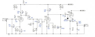
If you insist in using this circuit, do it like this.
It's no use to put a high impedance volume control where you wanted a low impedance output.
Also changed things to more resonable values.
Mona
Thanks a lot for the corrections. But i have a question. The diode on the cathode follower is rated for 100v max. I was told that when using a diode you always need to take one that has at least double the voltage rating than what is needed. Here the voltage could theoretical till 150v but in real life till 100v. Would it not be better to take a diode (a faster one than the 1N4007) that is rated for 200v or above? Something like this one: http://www.mouser.com/ds/2/348/rfu5tf6s-311349.pdf
It's not needed, the diode will only have a few volt's across it ( voltage betweenThanks a lot for the corrections. But i have a question. The diode on the cathode follower is rated for 100v max. I was told that when using a diode you always need to take one that has at least double the voltage rating than what is needed. Here the voltage could theoretical till 150v but in real life till 100v. Would it not be better to take a diode (a faster one than the 1N4007) that is rated for 200v or above? Something like this one: http://www.mouser.com/ds/2/348/rfu5tf6s-311349.pdf
grid and catode).
It's there to prevent the grid gettin positive during the tubes warm-up time, after
that the cathode will rise to a few volt's above the grid.
in fact a 1n4147 would do and it has less capacitance too.
BTW, i think the schematic has been altered, the one in post 26 is the correct one, with an
added cap on the output.
Last edited:
If you insist in using this circuit, do it like this.
It's no use to put a high impedance volume control where you wanted a low impedance output.
Also changed things to more resonable values.
Mona
plate resistance of the 12ax7 is very high, tube dependent and changes over time so that circuit, while it will work, is less than optimal.
good article to spend some time on: http://www.diyaudio.com/forums/diya...oise-thoroughly-modern-tube-phono-preamp.html
plate resistance of the 12ax7 is very high, tube dependent and changes over time so that circuit, while it will work, is less than optimal.
good article to spend some time on: http://www.diyaudio.com/forums/diya...oise-thoroughly-modern-tube-phono-preamp.html
Yes, that's the case with all circuits like this.The Ri from the tube is part of the RIAA network.The series resistance (470k) makes the it less dependent of the Ri.
Ri=40k...80k (±30%) changes Rs from 470+40=510k to 470+80=550k (±4%)
Mona
plate resistance of the 12ax7 is very high, tube dependent and changes over time so that circuit, while it will work, is less than optimal.
good article to spend some time on: http://www.diyaudio.com/forums/diya...oise-thoroughly-modern-tube-phono-preamp.html
It's an interesting read, and maybe something for an other project. But the goal for this one is to build an oldskool phono pre fully depending on tubes except in the psu. I know those circuits are not as hifi and stable as a hybrid one (many told me before), but i like the sound of it. As a kid i often listened to a Grundig Radiogram console with a turntable in it of the father of a friend wich is in no way hifi to todays standards, but the sound fitted me and still does and that kind of preamp is the one i like to build (in a better way). I also often listen to a Marantz 7C owned by friends, and this one does the same like the old Grundig did, but better.
I do already own a Marantz PM5004 amp with a surprisingly good (especially for the price) build-in phono pre and a self build Pacificateur ss preamp. So that (solid state) side is covered for the moment.
Yes, that's the case with all circuits like this.The Ri from the tube is part of the RIAA network.The series resistance (470k) makes the it less dependent of the Ri.
Ri=40k...80k (±30%) changes Rs from 470+40=510k to 470+80=550k (±4%)
Mona
Potentiometer P1 is also part of the RIAA compensation network -- think Thevenin equivalent with the build-out resistor R7 in your case, or R1 in Lipshitz.
I am curious to see whether the plate resistance of a tube changes much through time.
- Status
- This old topic is closed. If you want to reopen this topic, contact a moderator using the "Report Post" button.
- Home
- Amplifiers
- Tubes / Valves
- Is this a good phono preamp circuit to build?