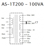
A few years back I ordered a cathode coupled amplifier from John Broskie, and a PS-18 power supply to run it. I'm also using the Antek AS-1T200 transformer ( yes, all just as in the article ") ). The transformer has two 200 volt and two 6.3 volt secondaries. For the heater supply I wired the two 6.3s in series and ended up with a steady 12.55 volts. The only tubes I have are 12AU7s, 5814s, E80CCs, and a few 12AX7s. So that part seems correct, given my tube selection.
). The transformer has two 200 volt and two 6.3 volt secondaries. For the heater supply I wired the two 6.3s in series and ended up with a steady 12.55 volts. The only tubes I have are 12AU7s, 5814s, E80CCs, and a few 12AX7s. So that part seems correct, given my tube selection.
But, I think I made a few mistakes on the high voltage section. First, I specified 250 volt capacitors, which seems too low. If I wire the two 200 volt secondaries in series for 400 volts I end up with 286 volts out. More than the caps rating. I'm also not sure I've wired the transformer to the HV section correctly. I connected the transformer wires to put the 200V secondaries in series ( just like I did for the heater section ), attached the wires that were spliced together to the center tap input on the power supply, then the remaining two wires to the front AC pads on the PCB. It seems correct, but I'm not sure.
I'll most likely be using 5814's for the input tubes and 12AU7 or E80CC for the output tube. At what voltage should I be running them? How do I adjust the RC filter to feed them the correct voltage, or calculate the correct resistor value to yield the right voltage?
I've read through the manual numerous times but don't see a clear answer. Any help would be greatly appreciated!
Cody
). The transformer has two 200 volt and two 6.3 volt secondaries. For the heater supply I wired the two 6.3s in series and ended up with a steady 12.55 volts. The only tubes I have are 12AU7s, 5814s, E80CCs, and a few 12AX7s. So that part seems correct, given my tube selection. But, I think I made a few mistakes on the high voltage section. First, I specified 250 volt capacitors, which seems too low. If I wire the two 200 volt secondaries in series for 400 volts I end up with 286 volts out. More than the caps rating. I'm also not sure I've wired the transformer to the HV section correctly. I connected the transformer wires to put the 200V secondaries in series ( just like I did for the heater section ), attached the wires that were spliced together to the center tap input on the power supply, then the remaining two wires to the front AC pads on the PCB. It seems correct, but I'm not sure.
I'll most likely be using 5814's for the input tubes and 12AU7 or E80CC for the output tube. At what voltage should I be running them? How do I adjust the RC filter to feed them the correct voltage, or calculate the correct resistor value to yield the right voltage?
I've read through the manual numerous times but don't see a clear answer. Any help would be greatly appreciated!
Cody
I'm still unsure…
Transformer → rectifiers → small C → medium R → big C → medium R → big C → R → …
This is called an cRCRC filtering chain. Each section drops the voltage (using its prior R) from the prior C and charges the next C. The low-pass-filter action therein significantly squashes the pulsating ripple of the previous stage. The LAST stage is used to power up the most sensitive section (the first stage of the preamp).
This is the "old fashioned, economical, but pretty darn good" method. Invented when higher value electrolytic capacitors became relatively inexpensive. And when medium-power carbon composite resistors came in 5 watt or higher power ratings, and moreover were cheap enough to be used either in series or in parallel to gain doubling, tripling or higher -ing of power ratings.
Remember, your preamp stages use a handful of milliamps typically per stage. This is a very modest amount of power delivery. Therefore (again) CRCRCRCRC… power staging is "good enough" for most.
HOWEVER - if you want to be something of a purist, substituting a series regulator for that first R can result in a very satisfying result in the noise-free-power department. This comment cannot provide the scope of such, but DIYAUDIO has gazillions of articles and the usual poppery of comments therein. Remember, all the RC stages are doing is [1] R = voltage drop like a small hole in a bucket of water, and [2] C = the next bucket, which is good at sustaining an average reservoir of current flow as well as providing far larger current than could be demand-squeezed out of a naked resistor. A bucket. Of electrons.
GoatGuy
A valve circuit designed for 250V should work OK on 286V without any modification, provided that capacitors have sufficient voltage rating.
Agreed.
The one curious thing tho' is that open-circuit he's reporting about 286 volts, I believe from 2 ea 200 VAC windings in series. Doesn't seem to fit. I'd expect that from 1 winding by itself (or the pair in parallel), thru solidstate rectifiers which have low drop. √(2) • VRMS - 2.8 volts for full wave bridge 4 diode rectification.
I'm also kind of questioning his lingo re: how the 2 secondaries were "series" connected. I think he's implying a
W1A → rectifier → + rail
W1B → W2A → "center tap"
W2B → rectifier → + rail
configuration. If so, and even if the 'rectifiers' are vacuum bottles, then the 286 volts is consistent with √(2) VPEAK and VRMS math. Vacuum bottle rectifiers, unloaded have a vanishingly small VFORWARD. So much so that they were once critical for high-accuracy instrumentation used in professional/scientific metrology.
Anyway… just random thoughts.
GoatGuy
New caps on the way
Hi Guys!
Thank you for the advice/help!. I will definitely look into a series regulator. I have a lot of stuff/parts/tubes laying around that need to be put to use, or sold. Going to try to use it first. The 500 volt caps will be here tomorrow. Removing solidly attached snap in caps from a thick board is no fun, btw.
The rectifiers in the PS are solid state.
W1A → rectifier → + rail
W1B → W2A → "center tap"
W2B → rectifier → + rail
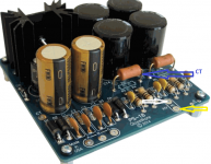
I believe this is how I wired the PS, but I've attached diagrams to show, just in case.
Hoping to get this one running then move on to better/more complicated after. Just wanted to be sure there weren;t any more fundamental errors before hooking the preamp to the power circuit. If 286 volts is safe/effective for 5814/12AU7/E80CC then I should be good to go once the right caps are in.
Thank you much!
Hi Guys!
Thank you for the advice/help!. I will definitely look into a series regulator. I have a lot of stuff/parts/tubes laying around that need to be put to use, or sold. Going to try to use it first
. The 500 volt caps will be here tomorrow. Removing solidly attached snap in caps from a thick board is no fun, btw.The rectifiers in the PS are solid state.
W1A → rectifier → + rail
W1B → W2A → "center tap"
W2B → rectifier → + rail
I believe this is how I wired the PS, but I've attached diagrams to show, just in case.
Hoping to get this one running then move on to better/more complicated after. Just wanted to be sure there weren;t any more fundamental errors before hooking the preamp to the power circuit. If 286 volts is safe/effective for 5814/12AU7/E80CC then I should be good to go once the right caps are in.
Thank you much!
Attachments
> Broskie, and a PS-18 power supply
Would be real handy to give a LINK, for those of us who do not have all of John's offerings memorized.
> a cathode coupled amplifier
Same question LINK.

The transformer he offers for PS-18:
"Output Voltage: Series: 230VAC CT@ 0.11A Parallel: 115.0VAC@ 0.22A"
With his suggested PT we would expect two (+/-) 168V DC outputs.
> two 200 volt secondaries
Then we expect nearly 282V. The stock 250V cap option is NOT intended for this transformer.
As a Line Amp, +/-250V-300V may be safe (I can't read the resistors) but seems way excessive.
Would be real handy to give a LINK, for those of us who do not have all of John's offerings memorized.
> a cathode coupled amplifier
Same question LINK.
The transformer he offers for PS-18:
"Output Voltage: Series: 230VAC CT@ 0.11A Parallel: 115.0VAC@ 0.22A"
With his suggested PT we would expect two (+/-) 168V DC outputs.
> two 200 volt secondaries
Then we expect nearly 282V. The stock 250V cap option is NOT intended for this transformer.
As a Line Amp, +/-250V-300V may be safe (I can't read the resistors) but seems way excessive.
Hi PRR ,
Apologies, I should have linked to the circuit. I went with the other transformer mentioned in his article as he didn't seem too fond of the Hammond. That being said, I believe I've figured out what I missed. I'm measuring unloaded voltage on the B- and B+ pads - where it currently reads equal to the rectified value of 286 volts. If I interpret random internet information correctly I wont see a drop in voltage until the load is connected, at which point it would be calculated with V=IR. Or Vout=Vrectified - Vdrop, or 286-(40ma*1K)=246
This made it easy:
https://www.ampbooks.com/mobile/amplifier-calculators/RC-ripple-filter/calculator/
I also interpret this to mean I would need to adjust my power supply accordingly for a 12AU7 or E80CC ( to keep it around 250 volts ), as the E80CC will pull a lot more current.
The 500 volt caps will be here tomorrow
Thank you much!
Cody
- Status
- This old topic is closed. If you want to reopen this topic, contact a moderator using the "Report Post" button.
- Home
- Amplifiers
- Tubes / Valves
- Question on building my first tube preamp power supply