Dear all
I am planning to bild a tube amp monoblock from an old Hammond HR-40 Amp i found on ebay.
I wand to use it as a hifi amp. Output transformers from esdcor are on the way for the original Hammond amp, so i am bound to the final 6v6 parallel stage design.
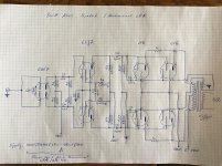
I would like to preamp with a 6SN7, followed by a parallel 6SJ7, then go into the Hammond 2x 2 parallel 6V6 stage.
I also want to re-use the power supply from the HR-40/LRA with parallel 5U4G and 280V output/295V B+
Could you please critically check/comment/correct my first approach? I am a greenhorn.
Thanks a lot and a happy new year.
Thomas
Just found out that there needs to be an additional ground connection between R3 and R4.
I am planning to bild a tube amp monoblock from an old Hammond HR-40 Amp i found on ebay.
I wand to use it as a hifi amp. Output transformers from esdcor are on the way for the original Hammond amp, so i am bound to the final 6v6 parallel stage design.
I would like to preamp with a 6SN7, followed by a parallel 6SJ7, then go into the Hammond 2x 2 parallel 6V6 stage.
I also want to re-use the power supply from the HR-40/LRA with parallel 5U4G and 280V output/295V B+
Could you please critically check/comment/correct my first approach? I am a greenhorn.
Thanks a lot and a happy new year.
Thomas
Just found out that there needs to be an additional ground connection between R3 and R4.
Attachments
Last edited:
Well, if i am not mistaken, the arrangement of the 6sn7 will not achieve a split phase since you are running that tube as each section as a voltage amp. Usually, one would put the pentode as the voltage amp going to the 6sn7 as the phase splitter. Check out vintage Mullard schematics. They used a ef86 to duo triode combo. Lots of examples of different output tubes. Eico liked 12ax7 to 6sn7, and the HF60 amp used ef86 to 6sn7.
Well, if i am not mistaken, the arrangement of the 6sn7 will not achieve a split phase since you are running that tube as each section as a voltage amp. Usually, one would put the pentode as the voltage amp going to the 6sn7 as the phase splitter. Check out vintage Mullard schematics. They used a ef86 to duo triode combo. Lots of examples of different output tubes. Eico liked 12ax7 to 6sn7, and the HF60 amp used ef86 to 6sn7.
Exactly. The Mullard 5-20 should be a good start. Use the 6SJ7 as the voltage amp and the 6SN7 as the driver/splitter.
The suggestion to deploy the 6SJ7 and 6SN7 in Mullard style small signal circuitry makes considerable sense. Merge the EICO HF87 and Mullard 5-20 together.
The I/P "padder" pot. in the HF87 is of particular importance. The 2 VRMS signal from a "standard" CDP will drive the 6SJ7/6SN7/6V6 tube complement into clipping, unless attenuated.
Full pentode mode "finals" yield the best open loop linearity, when g2 B+ is regulated. Therefore, read this LENGTHY thread and buy Tom's PCB.
I did not look at your schematic closely as the driver/splitter section of your scheme stood out as not feasible and so i noticed another "interesting" aspect of your schematic. You have what looks like some feedback from the secondary of the output trans that goes to the cathodes of the power tubes. While i don't have enough experience to know if that is feasible, i do know that i have not run across that scheme in the many, many schematics that i have perused. Tube circuits are probably only limited by one's imagination but again i might be mistaken and that running the fb to only the power tubes will probably not work well. The usual way would be to tap the 8 or 16 ohm secondary and run the fb globally, all the way to the first tube.
I suggest that you search push pull parallel 6v6 amp or el84. The el84 is essentially a 6v6 in a 9 pin format. I also suggest you subscribe to Tube Cad Journal. John Broskie likes to play with new and interesting tube circuits, as well as SS stuff. It seems that you want to do something different but that requires you understand the more basic stuff first, before diving into the esoteric. cheers.
I suggest that you search push pull parallel 6v6 amp or el84. The el84 is essentially a 6v6 in a 9 pin format. I also suggest you subscribe to Tube Cad Journal. John Broskie likes to play with new and interesting tube circuits, as well as SS stuff. It seems that you want to do something different but that requires you understand the more basic stuff first, before diving into the esoteric. cheers.
The cathode feedback idea is quite good. It's a very reasonable alternative to UL mode. A cathode feedback winding is another variation on the local NFB theme. Drive requirements increase, when the CFB option is exercised. A 6SJ7 voltage amplifier feeding a 6SN7 LTP will have plenty of gain.
Thank you for all these feedbacks.
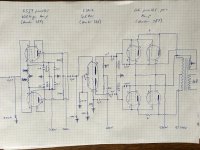
I have tried to adapt the schematic, 6SJ7 is now voltage amp prior to 6SN7 splitter followed by the 6V6 parallel pair.
I hope this is better.
The resistors of the voltage supply of the voltage amp and the splitter have been adapted to the 280VDC from the HR-40 power supply.
A schematic of the HR-40 will follow. I will no longer use the reverb unit and the opt will be replaced, i want to keep the powersupply inclufing/up to the c15 4uF cap.
Thanks for review of the adapted shematic
Thomas
Attachments
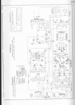
Attached the HR-40 / LRA schematic. There are two cirquits on this shematic, a bass cirquit and a treble cirquit. Both with a parallel pair of 6v6
I will no longer use the reverberation cirquit.
The original power supply is 280VDC and 295VDC B+. The power supply with the two 5U4G will be re-used.
This amp is said to be a push pull amp, for the treble cirquit, this seems to be correct, there is a 6sn7 splitter sort of included. For the bass it looks more like the 6sj7 are used as a voltage amp.
I plan to replace both cirquits, just leaving the 6v6 parallel pairs undisturbed.
Thomas
Attachments
No, you still don't have a phase splitter. Your 6SN7 stage combines elements from two different phase splitter designs in a way which ensures that it won't work. Are you just copying bits of circuits, or are you trying to understand them?I hope this is better.
In this redesign you have no need for the second 6SJ7. The 6SN7 does the driver duty. The phase splitter might work as it is but won't have the swing you'll need on the output.
To make this work you would likely have to move the 6SN7 as-is to the frontend and use the 6SJ7s as amplifiers for the output stage.
To make this work you would likely have to move the 6SN7 as-is to the frontend and use the 6SJ7s as amplifiers for the output stage.
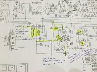
Eli is giving good advice, but a possible alternative plan would be to use the existing bass channel design with a few mods:
Delete C17, C21, and C22.
Ground V11 grid.
Replace R30 with 100K and ground the left end. Apply signal to V10 grid.
Replace R32 with a 7.7mA constant current source operating off the -18V rail.
These changes ought to produce a good wideband amplifier, depending on OPT characteristics. Sensitivity is hard to estimate because we don't have original OPT specs. Where will you obtain suitable OPTs?
Last edited:
> there is a 6sn7 splitter sort of included.
No. Review basic amplifier topologies.
The inputs are BALANCED lines from the organist console. (Recall that sometimes the console was at the far end of a long church from the tone cabinets. Medium/low Z and balanced was used so that the installer was not likely to find a hum-problem on-site when wires must follow power wiring.)
No "phase splitter" is needed in the power amp IF you can be sure your sources are well balanced, as Hammond did.
Also note that 6V6 G1 bias is gotten from a NEGative tap in the power supply, not grounded as you seem to show. If G is near ground and cathodes return to ground (through low-Z winding), the 6V6es will burn-up very quickly.
I missed that original schematic, sorry.
That's a pretty impressive power trafo, along with the choke I/P PSU filter. Hammond shows 6V6 anode B+ as 295 V. In HIFI service, PP 6V6s require a bit "taller" B+ rail than 295 V. That's easy enough to achieve. Replace the 5U4 rectifiers with 5AR4/GZ34s. Take the "raw" B+ from the connected pin 8s, not the connected pin 2s. That wiring works for both 5U4s and 5AR4s.") To ensure that residual hum level is low, the value of C14 needs to increase. Use a 105o C. rated 500 WVDC/100 μF. part. Fortunately, the volumetric efficiency of modern parts is very much greater than what Hammond used. For correct operation, choke I/P filters require that a CRITICAL CURRENT be drawn. That requirement is fulfilled by placing a bleeder resistance in parallel with the new C14. A series wired pair of 25 W./3000 Ω wirewound parts get the task done.
To ensure that residual hum level is low, the value of C14 needs to increase. Use a 105o C. rated 500 WVDC/100 μF. part. Fortunately, the volumetric efficiency of modern parts is very much greater than what Hammond used. For correct operation, choke I/P filters require that a CRITICAL CURRENT be drawn. That requirement is fulfilled by placing a bleeder resistance in parallel with the new C14. A series wired pair of 25 W./3000 Ω wirewound parts get the task done.
That's a pretty impressive power trafo, along with the choke I/P PSU filter. Hammond shows 6V6 anode B+ as 295 V. In HIFI service, PP 6V6s require a bit "taller" B+ rail than 295 V. That's easy enough to achieve. Replace the 5U4 rectifiers with 5AR4/GZ34s. Take the "raw" B+ from the connected pin 8s, not the connected pin 2s. That wiring works for both 5U4s and 5AR4s.
To ensure that residual hum level is low, the value of C14 needs to increase. Use a 105o C. rated 500 WVDC/100 μF. part. Fortunately, the volumetric efficiency of modern parts is very much greater than what Hammond used. For correct operation, choke I/P filters require that a CRITICAL CURRENT be drawn. That requirement is fulfilled by placing a bleeder resistance in parallel with the new C14. A series wired pair of 25 W./3000 Ω wirewound parts get the task done.I am currently thinking about Edcor output transformers cxpp50 3.4k
Eli is giving good advice, but a possible alternative plan would be to use the existing bass channel design with a few mods:
Delete C17, C21, and C22.
Ground V11 grid.
Replace R30 with 100K and ground the left end. Apply signal to V10 grid.
Replace R32 with a 7.7mA constant current source operating off the -18V rail.
These changes ought to produce a good wideband amplifier, depending on OPT characteristics. Sensitivity is hard to estimate because we don't have original OPT specs. Where will you obtain suitable OPTs?
I see, this means I will stick to the original power transformer, edcor alternatives like the xpwr149 which would be better for our 220V supply do not offer the -18V output...
I want to use the amp on a parasound p/fet preamp with 10v output and 420ohm output impedance.
I want to use the amp on a parasound p/fet preamp with 10v output and 420ohm output impedance.
> there is a 6sn7 splitter sort of included.
No. Review basic amplifier topologies.
The inputs are BALANCED lines from the organist console. (Recall that sometimes the console was at the far end of a long church from the tone cabinets. Medium/low Z and balanced was used so that the installer was not likely to find a hum-problem on-site when wires must follow power wiring.)
No "phase splitter" is needed in the power amp IF you can be sure your sources are well balanced, as Hammond did.
Also note that 6V6 G1 bias is gotten from a NEGative tap in the power supply, not grounded as you seem to show. If G is near ground and cathodes return to ground (through low-Z winding), the 6V6es will burn-up very quickly.
I have adapted the drawing according to Mike and Elis comments and the ones from Eli.
But I have some questions,
When removing/deleting c17, c21 and c22, do I leave the connection/respectively remive and bridge whre the caps where?
V11 grid grounding, in addition to the existing cirquit over R31 from signal 2?
Rewiring v10 frim signal, directly go to v10 grid, but leave connection to ground via R30 100k?
What element is to be used as 7.7mA constant source on the -18v tab?
Sorry... Just newbie questions, i have no clue yet.
This system does not have a splitter or driver, right?
The 6sj7 in this case work as a preamp, do they?
Best regards and a happy new year
Attachments
I have taken a look at the preamp schematics of Hammond organs to which this tone cabinett amplifier (HR-40 LRA) was connected.
To me it seems that the organ preamps have a voltage amplification stage and a phase splitter stage.
This means the tone cabinet amplifiers where fed with phase splittet signals. This explanes the two signal in pins on the am schematic.
If this is the case, it would mean that
- the driver of the treble stage, made of a 6sn7 is just used to control the output, since it has a 30000ohm potentiometer
- the two 6sj7 of the bass stage are used to increase the voltage of the bass cirquits, as a preamp of the two phases
Could this be an explanation of the cirquits?
In this case wouln't it make sense to just add a simple voltage amplifier stage with a 6sj7 after signal in, followed by a phase splitter with a 6sn7, and then go to the driver stage of the original hammond treble stage?
Of course with the adaptions prposed by Mike and Eli
Thomas
- Status
- This old topic is closed. If you want to reopen this topic, contact a moderator using the "Report Post" button.
- Home
- Amplifiers
- Tubes / Valves
- Need expertise for my first project, 6SN7-6SJ7-6V6