Hello all,
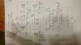
I've cobbled together my first self-designed amp. The irons and 6973's were taken from a Silvertone console stereo, so the amp was designed around those components. The PT had two HT secondaries, one at 730VCT (which fed two 12AX7's and the 6973's), and the other at 165V (which fed all the radio tubes). Given the fact that I had the extra winding, I figured I'd might as well use it and put the extra current to use powering the primary gain stage, the PI, and a secondary gain stage. It starts with a standard grounded cathode 12AX7 stage. I followed this with a cathodyne with "fixed" bias based on the ideas presented by Merlin Blencowe at Valve Wizard. Next, I used both halves of 6DJ8 to add some gain to the cathodyne stage outputs and fed that into a run-of-the-mill cathode biased push-pull topography. The three initial stages (or possibly just the 6DJ8's) will be fed by the 165V secondary, bridge rectified to hopefully provide about 225V.
Would any of you kind folks be willing to give me notes? Advice? Comments?
I've attached a picture of the schematic which is hand drawn because it was done at work. I haven't put the PSU schematic together yet, nor have I settled on a feedback circuit, so it's all very very raw at this point.
Attachments
Would any of you kind folks be willing to give me notes?
There is a problem with the direct coupling from the phase splitter to the 6DJ8.
Use coupling capacitors instead.
It seems like they're frequently omitted in others' schematics (the Williamson Amplifier for example). I was not clear on the reasoning behind that, but I went with what seemed to be the norm there. My instinct tells me to decouple the stages, but if someone out there can't give me a compelling reason why I shouldn't then I will make that amendment.
It seems like they're frequently omitted in others' schematics (the Williamson Amplifier for example).
See this schematic for an example of an alternative coupling approach which is in this circuit between first and second stages.
http://ampslab.com/SCHEMATICS/LowRes/McIntosh_MC40.jpg
This requires a larger cathode resistor for a proper operating point.
Last edited:
As a design issue, the pentode output stages without feedback will have a huge output source resistance, making the amplifier extra sensitive to speaker impedance variations. Fun maybe, but not hi-hi. Also, you're going to have a whole heck of a lot of gain, maybe way more than you'd want.
All good fortune,
Chris
All good fortune,
Chris
For your circuit, the reason to use coupling caps is the following:
There is a higher voltage on the plate of the 6N1P than on the cathode of the 6N1P.
So, the grids of the 6DJ8 are at very different voltages. One 1/2 of the 6DJ8 will be turned on hard, and the other will be turned on less or cut off (even with no signal). And then either that 510 Ohm cathode resistor is going to be hot, or the 6DJ8 is going to be hot, or both (actually the 10k plate resistors may save the day). But the coupling caps are required in this particular circuit to prevent such bad imbalance and over dissipation in the 6DJ8.
If there is ripple on the 225V B+, it will be on the divider of the 6N1P grid, and so it will be on the cathode and plate of the 6N1P. You will have to filter the B+ better, or split the top resistor to the 6N1P grid in two, and put a filter capacitor to ground there.
But also, the parallel resistance of the 6.8M and 2.7M is larger than 1 Meg (the max grid resistance for the 6N1P). Just re-figure the divider for the same 2.5:1 ratio, but where the parallel value of the top and bottom resistors is 1 Meg or slightly less.
The 33k Ohm grid stopper resistor on the 12AX7 grid will limit the high frequency response. The 12AX7 grid to plate capacitance is 1.7 pF. With a gain of perhaps 60, that will be (60 x 1.7pF + 1 x 1.7pF) = 104 pF. -3 dB at 46kHz, or -1dB at 23 kHz.
That may be OK, especially if the other stages have a wider frequency response.
It may help to reduce or eliminate any ringing in the output transformer due to the slew limit it puts on a square wave input.
Ringing at the amp output with a square wave input is a whole other subject, not to be
explained here today.
One more thing, because the amp uses pentode output stages combined with no negative feedback, the damping factor will be fairly low. How that effects the sound will be firstly
dependent on the loudspeakers impedance versus frequency, and secondly on the output transformer's characteristics, like primary inductance, distributed capacitance, and leakage reactance.
Of course any output transformer's characteristics also effect any kind or type of output stage that uses transformers.
I am just about to try building an amp with a pentode output stage.
I plan on doing several experiments, bench testing, and some listening too.
Let us know how your amp works and sounds when you get it up and running.
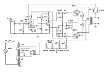
The 6973 amplifier circuit in this publication could save you some grief. By using fewer stages, it will be easier to stabilize with the feedback loop closed around output transformers other than specified. The 7199 can be substituted with 6GH8 or other similar types as long as you're willing to optimize the screen resistance (R3).
Seems like far too many stages for the application, a single voltage amplifier stage and cathodyne phase splitter are all that is really required with the 6973 which is has pretty high sensitivity.
You could consider the Mullard 5-20 topology with low mu triodes.
Negative feedback with pentode or UL connected outputs is derigeur to reduce output impedance and gain to reasonable levels.
You could consider the Mullard 5-20 topology with low mu triodes.
Negative feedback with pentode or UL connected outputs is derigeur to reduce output impedance and gain to reasonable levels.
Wow! Thank you all for your responses, especially 6A3sUMMER -- that was informative and instructive. I do appreciate how non-judgmental the DIY audio community can be. The coupling caps between the cathodyne and the 6DJ8's will certainly be added.
To be clear, I was absolutely planning on adding negative feedback. I simply hadn't yet decided how much of it I wanted. I know that a second gain stage may be overkill. I thought that perhaps that would allow me to up the feedback without sacrificing much gain. Once I get around to breadboarding everything, I may well end up scrapping that, it just seemed a waste to not use that extra HT tap. I suppose I could throw in some tone controls, or some magic eye silliness in lieu of another gain stage.
To be clear, I was absolutely planning on adding negative feedback. I simply hadn't yet decided how much of it I wanted. I know that a second gain stage may be overkill. I thought that perhaps that would allow me to up the feedback without sacrificing much gain. Once I get around to breadboarding everything, I may well end up scrapping that, it just seemed a waste to not use that extra HT tap. I suppose I could throw in some tone controls, or some magic eye silliness in lieu of another gain stage.
The answer to your question is quite simple. The scrapped amp that I got all of these components from had a quad of strong testing 6973's. Why not stick with tubes that the OT's and PT were originally designed to work with? Plus, Electro Harmonix sells new production 6973's.
If you are going to add a tone control state, just keep in mind that you must put it outside of any negative feedback loop of the amplifier.
i.e. tone control stage, then the amp with negative feedback.
Putting the tone control inside the amp feedback loop will tend to do two things:
Flatten the frequency response (undo the tone control effect).
Cause oscillation because of the phase shift of the tone control (at some frequency there will be positive feedback, not negative feedback).
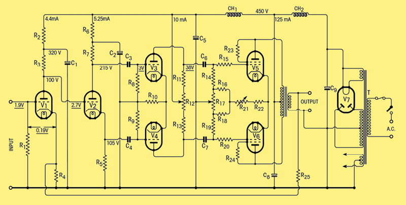
Well, this is what I landed on in the end. I'm not exactly reinventing the wheel here, but I think it will turn out well enough. I've scrapped the second gain stage and I'm not going to use tone controls (which I really don't like, even on commercial amps). I've added a pretty basic global NFB circuit, which may need post assembly tweaking. I've also ditched the 6N1P as the phase splitter, so I can just use the other side of the 12AX7's. Commensurate with that, I've also taken the extra HT winding out of the equation.
How does everything look now?
I haven't worked out the PSU yet, which is going to prove something of a challenge. It should put out around 450V after the rectifier, and the choke I have on hand will only bleed 27 volts or so off of that. I'm not sure how I'm going to drop the voltage to a manageable level without using ridiculously high-wattage resistors. Any suggestions? I think the original amp used SR's off the HT to feed the grids, thus pulling the voltage down. I'm cathode biasing, so I don't know where to put that excess energy.
Lastly, I still want to make use of that extra tap and I have some magic eyes laying around. Would tapping the output tubes as their input change the overall output impedance; and for that matter, how does one connect those in a push-pull configuration where they will see the whole signal? Is that even possible?
Sorry to be so full of questions. I hope someday that I can be knowledgeable enough to help others through their problems.
Attachments
The 6.8K and 2.7K appear in parallel as part of the AC load on the preceding stage and are far too low - 680K and 270K would be more reasonable. It the plate voltage in the first stage is around 100V or so omit the coupling cap and those two resistors. I would increase the value of the cathode and plate resistors in the phase splitter to 100K or so..
That 0.1uF cap across the 18K feedback resistor is not going to fly either, start without it and you may or may not need a few hundred pF there depending on the output transformers.
That 0.1uF cap across the 18K feedback resistor is not going to fly either, start without it and you may or may not need a few hundred pF there depending on the output transformers.
Two big cautions:
1. You do not have a power supply bleeder. Use 2 each 25k 5 Watt resistors across the B+ to ground. This will bleed the voltage down. You do not want to work on the amp with charged capacitors. Check for remaining B+ with a DC multimeter before you get back into the circuitry.
2. For Pentode operation, be sure Always to have a load on the output secondary of the transformer, either your loudspeakers, or an 8 Ohm power resistor.
Failure to do this can result in shorted output transformer, dead output tubes, or both.
Now for other considerations:
You need to apply the negative feedback to a resistor, and that resistor to ground (i.e. 100 Ohms). The other end of the resistor needs to go to the bottom of the 3k 47uF combo (lift them from ground). So, you have cathode, 3k/47uF, 100 Ohms, ground. The feedback goes to the junction of the 100 Ohms and 3k/47uF. The feedback resistor will have to be adjusted. And the feedback capacitor will have to be much smaller than 0.1uF.
If you first want to try it without feedback, then triode wire the 6973s (change the screen resistors from 1k to 100 Ohm, and connect them to the respective plates of the 6973s).
You might find triode mode very satisfying (and easier than calculating and trimming negative feedback, and stabilizing it according to the output transformers and the rest of the circuitry's phase versus frequency).
Triode mode is less power out, but has better damping factor without negative feedback.
The amount of negative feedback required for Pentode mode is rather large if you want the same damping factor as un-fedback triode mode.
The easy way to lower the B+ is to use choke input. Remove the 40uF cap, and use one more series Resistor with the 40uF cap to ground (choke, RC, RC, RC).
The critical inductance required for the choke is 350/mA.
For example, for 100 mA draw, that would require a 3.5 Henry choke. Use the next value up, i.e. 5 H. Be sure the choke can take the voltage, and the current.
For a cap input supply like you have drawn, the max voltage it will rise to (unloaded) is 1.414 times the RMS V. The DCR of the choke, and the resistors will drop it down from there, according to the current through them.
1.414 * 365 = 516VDC
For a choke loaded supply, the max voltage at rated load is 0.9 * the RMS V.
0.9 * 365 = 328.5V The DCR of the choke, and the resistors will drop it down from there, according to the current through them.
Now, suppose you want a B+ between the two configurations. Use capacitor input,
but less than 40uF.
Example:
Xc = 1/(2 * Pi * F * C) This is the capacitive reactance.
A 2 uF cap has 663 Ohms capacitive reactance at 120 Hz (120 Hz is full wave rectification).
If the current draw is 100mA, that will be 663 * 0.1 = 66.3V peak to peak ripple.
The average is 33V between peak and trough.
1.414 * 365 = 483V
483V - 33 = 450V.
Be careful, the first capacitor and first choke can resonate. Do not resonate them at 120Hz.
Resonance is 1/(2 * pi * (Root of L * C)) = Hz
1/(2 * Pi * (root of 5 Henrys * 2 uF))
1/(2 * Pi * (0.00316) = 50.3 Hz OK
0.5 uF and 5 Henrys resonates at 100.7 Hz (Not OK, too close to 120 Hz)
6 Henrys will have similar performance as the 5 Henry examples above).
I did Not check the load lines and particulars of the 12AX7 and 6973 parameters,
for the resistances and transformer primary impedance you have selected on the schematic.
I am planning on designing a current sourced/cathode coupled 12AY7 or 12AV7, or even a 12AX7 phase splitter driving push pull triode wired KT66s for a low power amplifier (trying for more finesse than power; and for lower power dissipation on the KT66s). There will be lower gain because of the cathode coupling, and triode wiring, but will be driving from the 3V peak from a CD player.
365 * 1.414 = 516V. Loading will bring it down.
- Status
- This old topic is closed. If you want to reopen this topic, contact a moderator using the "Report Post" button.
- Home
- Amplifiers
- Tubes / Valves
- Soliciting advice for my first design (push-pull 6973)