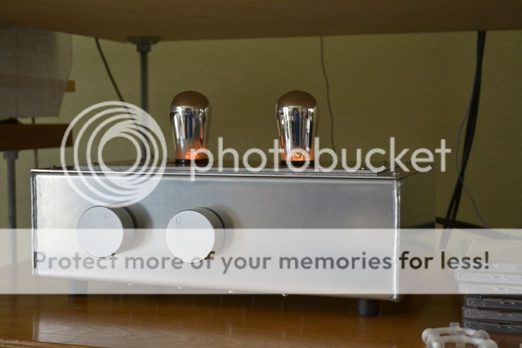
After a few days of using the preamp, checked the current and the voltages, I can finally say that it is working properly and I definitely like the sound!! Thanks again! Using UX201 A at the moment. Please see pics below of my humble project.
[URL=http://s98.photobucket.com/user/amandaraer4532/media/DSC_0097_zps2cbgqxpt.jpg.html]
An externally hosted image should be here but it was not working when we last tested it.
[URL=http://s98.photobucket.com/user/amandaraer4532/media/DSC_0097_zps2cbgqxpt.jpg.html]
An externally hosted image should be here but it was not working when we last tested it.
[/URL]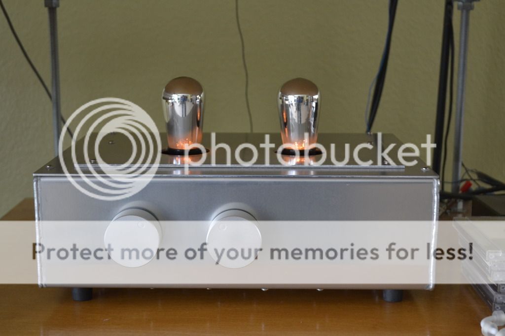
You have not seen yet graphite anode 801 prices. :-(
Compared to their prices 201a is a "cheap thrills".
The graphite anode GE 801A with micanol base that's THE tube! Unfortunately it's rare and expensive.
Looks great. I'm collecting parts for the same design. I really like hearing the listening impressions of those that have built it.
Ale's 01A Gen 2 preamp is the state of the art, as far as I'm concerned. I'm surprised at how much better the gyrator sounds than interstages, e.g. Lundahl LL1635. More detail, clearer sound. I haven't tried the exotic interstages - amorphous core etc.
It's not a difficult build - PCBs for the Gyrator and Rod's regs. I build in 2 chassis - signal and PSU/filaments. PSU is LCLC and filaments are LC. I use Hammond chokes - 155J for B+ and 159Y for filaments. The B+ needs a 20K bleeder resistor for critical inductance, since the current through the preamp is so tiny.
Thanks Andy.
I have the filament regs and the gyrator boards. Haven't given the power supply much thought yet but I think I have some transformers and chokes around that will work. My present line stage is a single 37/76 triode with Gary Pimm type CCS's for the anode loads. I like the sound but am hoping for good things from the 01a.
I've used Lundahl's LL1660 IT's with the amorphous core. They are really good sounding I think. I updated from the regular version and it was a truly breathtaking improvement. I also have a pair of O-netics IT's which I believe use M3 cores. They give the Lundahl's a good run for the money.
John
Last edited:
Earthing the PSU
Hi Abe,
This is what I know from the literature. Do not connect directly between HV ground to Earth.
Suggested to use Capacitor 0.1uF/275AC and Resistor 120 ohms/0.5W in parallel connection. One is connected to HV ground and another end is connected to Earth. Chassis is connected to earth.Signal ground isn't connected to chassis.
Best Regards
JJ
Hello guys,
First off, I am building a 01A preamp base on Ale Moglia's (Bartola Valves)design. The schematic is this:

The only difference I made is to replace the 47K resistor to a 100k pot(volume control).
For power supply, I am using the same PSU I have been using, with no problems whatsoever, with my Type 26 preamp in a two chassis set up with HV from a tube rectified(AZ1)arrangement, plus two filament regulators(Rod Coleman's) using 16Vac transformer per to each set of diode rectifiers.
An umbilical cord is connected to the PSU to the main preamp chassis. I am getting 202V B+(LCLCLC) and 25V DC for each filament supply measured at the iNPUT of the Rod Coleman boards.
Here is the problem. Looking back at the schematic, I can measure 4,8V at the top of the filament resistor and 8.11 V at the cathode of the 201A, and 118 at the plate with respect to ground(0 V) and 30 mV across the resistor R5. If I flip the SW1, it takes the tube rectifier out with a flash. If I connect an interconnect at the output of the preamp to an input of say another amp who's Ground(0V) is connected to chassis ground(IEC ground), it takes the rectifier again. In other words, as soon as I have the chassis ground (IEC) connected to my 0V, it destroys the rectifier!
Also, the 4.85V is the minimum I can get from the Coleman Reg adjustment (using 3.9 ohms R1) and measuring from the Filament Input(+ and -) on the board, I am getting 25Vdc! Why is it too high?
Chassis is aluminum. Heat sinking is to the chassis, umbilical cord is a Neutrik 8 Pole with 1+ and1- as Filament Supply 1, 2+ and 2- as B+ and 0V, 3+ and 3- as HV 0V and IEC safety ground, and 4+ and 4- as Filament Supply 2.
Trying to seek help as I lost three AZ1's already and this project is getting too expensive
Thanks!
Abe
Hi Abe,
This is what I know from the literature. Do not connect directly between HV ground to Earth.
Suggested to use Capacitor 0.1uF/275AC and Resistor 120 ohms/0.5W in parallel connection. One is connected to HV ground and another end is connected to Earth. Chassis is connected to earth.Signal ground isn't connected to chassis.
Best Regards
JJ
- Status
- This old topic is closed. If you want to reopen this topic, contact a moderator using the "Report Post" button.
- Home
- Amplifiers
- Tubes / Valves
- Problem With 01A Preamp (Losing Rectifiers)