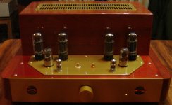
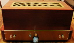
This is the project I just have finished. Oak wood and aluminum are used at case design, schematics is with positive and negative rails. Very satisfied with sound. I show the basic schematics, as built version can differ in shunting measures.
Attachments
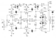
Nice build, but E88CC-s on 300v rail (actually 350, because of the - 50Vsupply) ?
I dunno......
Its operating point is 200V plate voltage, and signal swing at the plate is few volts only.
I've understood E88CC datasheet so, that 1,5W max dissipation per plate (3W in total), but if one goes above 1,5W at one plate, up to 1,8W, then on the second plate only 0,2W are allowed (2W in total). Maybe I am wrong, but I like the sound at present.Maximum anode dissipation of E88CC is 2 watt when both halves are used; your OP gives 2,6 watt of dissipation. Not good for life expectancy.
I've understood E88CC datasheet so, that 1,5W max dissipation per plate (3W in total), but if one goes above 1,5W at one plate, up to 1,8W, then on the second plate only 0,2W are allowed (2W in total). Maybe I am wrong, but I like the sound at present.
You are right provided it is a real E88CC.
The 10000 hours life expectancy test was actually done with 90V anode voltage and 15 mA anode current (i.e. 1.35W per plate). 200V anode voltage is also within the max specified 220V (which can be 250V if plate dissipation is 0.8W or less).
... provided it is a real E88CC.
Hope so, I use Philips Miniwatt SQ gold pins. Can test also Telefunken, have a pair.
You might replace R5 with a higher value to get some 100-120 V at the E88CC anodes.
The potential voltage swing with 200 V is not necessary to drive the next stage, and actually not realistic without introducing grid current.
When checking Philips E88CC datasheet you should have 3,5 V grid bias / 7 mA current at some 130 V anode voltage.....
The potential voltage swing with 200 V is not necessary to drive the next stage, and actually not realistic without introducing grid current.
When checking Philips E88CC datasheet you should have 3,5 V grid bias / 7 mA current at some 130 V anode voltage.....
Last edited:
You might replace R5 with a higher value to get some 100-120 V at the E88CC anodes.
The potential voltage swing with 200 V is not necessary to drive the next stage, and actually not realistic without introducing grid current.
When checking Philips E88CC datasheet you should have 3,5 V grid bias / 7 mA current at some 130 V anode voltage.....
Agree, some numbers on the schematics are not exactly "as built", the schematics shows basic approach. Actually the grid bias of e88cc comes to a bit more than 3,5V.
I have arranged a brief "wife test", which kind of tubes she prefers (emotional vocal recording):
1) E88CC Telefunken gold pins
2) E88CC Philips Miniwatt SQ gold pins
3) 6N23P-EV Russian 1972 year Reflector (shining pins, covered possibly rhodium)
The choice is Philips, 1) and 3) are closer to each other. 3) are not well heated up, just from the box.
2) seem to show more balanced sound, 1) and 3) seem to show some tonal inhomogenuities, maybe a bit "brighter".
However, conclusions are subjective.
Last edited:
- Status
- This old topic is closed. If you want to reopen this topic, contact a moderator using the "Report Post" button.
- Home
- Amplifiers
- Tubes / Valves
- PP amp E88CC - 6N8S - 6GB8