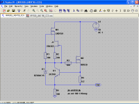
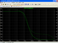
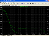
Yes, DN2540 is just fine.DN2540 subthreshold model clearly gives more accurate simulations as they are closer to some measurements, however I have not a clue about DN2530.
Just as Ian's model for IXTP01N100D
Last edited:
Hi Poplilin
I like the cheap parts solution. 2SK362 is now discontinued but 2SK170 could probably replace it... or maybe others.
Ian
I like the cheap parts solution. 2SK362 is now discontinued but 2SK170 could probably replace it... or maybe others.
Ian
Hi Ian
Glad to know that, I like it too. I use 2SK362 because it is the only cheap FET in my stock, 2SK170 is even better.
Glad to know that, I like it too. I use 2SK362 because it is the only cheap FET in my stock, 2SK170 is even better.
So here is another thought with regards to current source vs gyrator - are there other parameters that are different besides the PSRR?
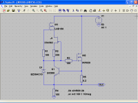
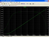
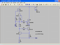
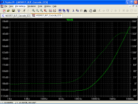
First picture is a current source, and the second is a gyrator using the same FET (MMTD1N50T).
There is a noticeable difference in harmonics, IMD, and the noise floor between the two.
How do these effect the perceived performance of the amp?
First picture is a current source, and the second is a gyrator using the same FET (MMTD1N50T).
There is a noticeable difference in harmonics, IMD, and the noise floor between the two.
How do these effect the perceived performance of the amp?
Attachments
Last edited:
Besides the PSRR, I should add self generated noise.
Other parameters such as impedance are directly related.
Please forgive my ignorance, but I am still thinking about measuring harmonic distortion on a device that attenuates, say 100 dB, the 1 KHz fundamental.
I assume that your graphics are from the complete stage (CCS/Gyrator) + Valve, otherwise -10 dB @ 1 KHz is a very poor performance.
BTW, I did a Google search for MMTD1N50T and nothing happens.
The 1KHz is the test signal, it is not suppressed. This was a test of a complete amplifier for harmonic distortion.
typo on the pn:
Datasheet Archive
typo on the pn:
Datasheet Archive
The 1KHz is the test signal, it is not suppressed. This was a test of a complete amplifier for harmonic distortion.
That explains all, my fault, sorry. I meant that does not make any sense to measure harmonic distortion on a circuit that has a very high attenuation.
Thinking of a typo, I did some search without first and last character, but Google works not so great on this side of the world, maybe connectivity also help to that, last night Internet connection was intermitent.
Sometimes mathematical models from the web has errors, in my case IRF830 model had a syntax error, once corrected, the circuit of post#61 does not behaves too well.
See here for details of model.
http://www.diyaudio.com/forums/software-tools/300703-help-verifying-capacitance-mosfet-model.html
See here for details of model.
http://www.diyaudio.com/forums/software-tools/300703-help-verifying-capacitance-mosfet-model.html
why you do not use P transistors? You should get better results, at least avoiding of bias currents flow into signal lines. (if your goal is max impedance)
why you do not use P transistors? You should get better results, at least avoiding of bias currents flow into signal lines. (if your goal is max impedance)
i) Uncertainty principle: When I find a good idea I do not find good mathematical models, and when I find the models I am too dumb to have a good idea. 😛😀
ii) HV P-MOSFETs do not abound, following Rod Coleman's advice I tried the FQP3P50 with poor results.
I have no formal education in electronics, but seems to me that modern MOSFETs has tons of transconductance and low capacitances are a weak advantage, so the last cascode is a natural approach, my only doubt is the useness of C1.
But hey, results are great, just compare with DN2540 cascode
http://www.diyaudio.com/forums/tubes-valves/299317-yet-another-ccs-4.html#post4898417
Last edited:
- Status
- Not open for further replies.
- Home
- Amplifiers
- Tubes / Valves
- Yet another CCS
