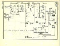
I've just picked up a german amp of unknown origin, that judging from the cap date stamps, must have been made in 1948. Wanting to rebuild it with as few changes as possible to make it suitable for use as a guitar amp, I looked at amps of the same period that also use a 6SJ7 input - Gibson/National-Valco/Ampeg. The one schematic posted below of the Natioal 1205 struck me as odd, as I've not encountered that set-up before......the screen grid is taken to the cathode of the following stage.....although I've got a few inklings as to what might be happening, this is out of my comprehension.....could someone please explain it to me.


Last edited:
Pentode gain is a function of G2 voltage.
For extra high gain of very small signals, you want low G2 voltage.
Common G2 dropper bias is hard to get WAY low.
I have seen a 2-stage guitar amp where G2 was got from power tube cathode. Never saw it with a 6SN7, but why not? 5V-10V at G2 is not wrong for <0.5V signals at G1.
For extra high gain of very small signals, you want low G2 voltage.
Common G2 dropper bias is hard to get WAY low.
I have seen a 2-stage guitar amp where G2 was got from power tube cathode. Never saw it with a 6SN7, but why not? 5V-10V at G2 is not wrong for <0.5V signals at G1.
I believe that is backwards. The lower G2, the lower the gain.
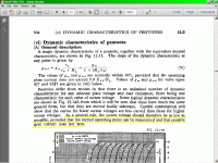
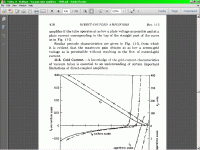
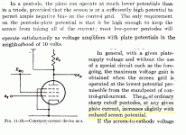
No. Pentode transconductance tends to be increased at lower screen voltages, as it is said in the Radiotron and many other books. Langford Smith suggest to use as lower screen voltages as grid current is not started. I checked it by myself and is true.
Also, it is not mandatory to return grids to cathodes. As there exists both positive and negative currents in the grid, no resistor to cathode forces them to be equal, although it is uncertain the grid voltage at this happens, and then, the bias point is also unpredictable.
Low G2 voltage = high plate voltage swing and gain (but low current gain) Okay, got it.
My concern was that the screen current draw, not being isolated from the source of voltage at the cathode of the 6SN7 by (an expected) larger resistor and bypass cap, would cause a drop over the cathode resistor, and swing the bias setting of the 6SN7 in some forwards sent NFB loop.
My concern was that the screen current draw, not being isolated from the source of voltage at the cathode of the 6SN7 by (an expected) larger resistor and bypass cap, would cause a drop over the cathode resistor, and swing the bias setting of the 6SN7 in some forwards sent NFB loop.
They are using the low voltage at the cathode, to biasing the screen, and then, saves the cost and power wasted in an independent resistor. If you like, you can add it, and the bypass condenser in the screen, as usual.
In the schematic, it calls my attention, that a 5Y3 to energize a couple of 6L6's is a bit small. I would use a 5U4.
In the schematic, it calls my attention, that a 5Y3 to energize a couple of 6L6's is a bit small. I would use a 5U4.
Last edited:
http://www.r-type.org/pdfs/6sj7.pdf
The bottom of page 4 shows typical Gm vs G2 voltage. As the G2 voltage decreases, Gm decreases.
Are you saying that below some point a curve (not shown) on the graph (below 50V G2) Gm increases above the G2=50V curve?
The bottom of page 4 shows typical Gm vs G2 voltage. As the G2 voltage decreases, Gm decreases.
Are you saying that below some point a curve (not shown) on the graph (below 50V G2) Gm increases above the G2=50V curve?
No, you're right, gm does decrease as Vg2 is reduced. However, reduced screen voltage allows you to use an enormous anode resistor while maintaining reasonable linearity. e.g. although gm is very low, you could use a 1Meg anode resistor and so get oodles of gain nevertheless, and a very efficient circuit since the current would be tiny. This was commonly called 'starved' pentode operation (today the term is more often used to describe any valve circuit that uses unusually low voltages, not just low screen voltage). Having said that, the OP's circuit is not using an enormous anode resistor, so his pentode is not really exploiting this technique.Are you saying that below some point a curve (not shown) on the graph (below 50V G2) Gm increases above the G2=50V curve?
Last edited:
- Status
- This old topic is closed. If you want to reopen this topic, contact a moderator using the "Report Post" button.
- Home
- Amplifiers
- Tubes / Valves
- Which pentode mode is this?


