Dear folks,
I measured 100 ECC803S tubes in "Quick-Test" using the brilliant u-Tracer.
The first aim is to sort out tubes which are to far away from typical characteristics defined in the datasheed.
The second aim is to find a pair of tubes wich match best all four systems.
For that I extract Ia,mu,Ra and Gm from uTracers report file and put the data to an excel sheet. Now I´m little stucked by evaluate the data to get the requested results.
To identify matching systems within a tube, I simply add all values ( Ia,mu,Ra,Gm) of one system. Next I divide the sum of both systems. If the result is 1 both system matches exactly. Sorting the "System deviation factor" of all tubes I get a list of tubes which are matching. Hope this is right
But quite more difficult is to identify tubes which are out of tolerance. The first question is: What is a acceptable tollerance ? The manufactor "JJ-Electronic" don´t not provide any information.
Example:
Tube #4 Ia1=1,59mA Ia2=0.92mA. Difference is Ia1 +33%, Ia2 -23%,
Is this a "bad" tube because the difference of both Systems is in sum 56%?
Whats about the other values. Which can be used to find out the "bad" tubes?
Attached you can find the excel sheet with all data...
Thanks a lot for every hint or tipp!
best regards
Karsten
I measured 100 ECC803S tubes in "Quick-Test" using the brilliant u-Tracer.
The first aim is to sort out tubes which are to far away from typical characteristics defined in the datasheed.
The second aim is to find a pair of tubes wich match best all four systems.
For that I extract Ia,mu,Ra and Gm from uTracers report file and put the data to an excel sheet. Now I´m little stucked by evaluate the data to get the requested results.
To identify matching systems within a tube, I simply add all values ( Ia,mu,Ra,Gm) of one system. Next I divide the sum of both systems. If the result is 1 both system matches exactly. Sorting the "System deviation factor" of all tubes I get a list of tubes which are matching. Hope this is right
But quite more difficult is to identify tubes which are out of tolerance. The first question is: What is a acceptable tollerance ? The manufactor "JJ-Electronic" don´t not provide any information
.Example:
Tube #4 Ia1=1,59mA Ia2=0.92mA. Difference is Ia1 +33%, Ia2 -23%,
Is this a "bad" tube because the difference of both Systems is in sum 56%?
Whats about the other values. Which can be used to find out the "bad" tubes?
Attached you can find the excel sheet with all data...
Thanks a lot for every hint or tipp!
best regards
Karsten
Attachments
You have gathered some good data. But unfortunately, deciding what is good or bad is entirely up to you.
Tube manufacturers do not publish the limits for specifications. They must have some limits to decide what they think is good or bad - but these limits may or may not be good enough for what you need. I seem to recall historically normal limits were on the order of +/-20% for parameters like gm and mu...
So I guess to set your own limits, you need to consider how the parameter variations will impact the circuit the tube is used in. For example, in one circuit, gm might need to be closely matched, while Ip might not matter as much. Or, the opposite might be true.
Not the answer you were hoping for, I expect.
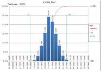
For what it's worth, we do this in semiconductor manufacturing all the time. Normally we will look at the distribution of measurements of each parameter separately. Then we set limits based on a combination of system circuit requirements (specs) and yield loss (how many parts we would need to throw away at a given set of limits). That's how we set the upper and lower limits for parameters on an IC datasheet.
The attached image shows a typical distribution. Each bar shows the population - the number of parts - that had that parameter measured within a particular "bin". I think if you were to plot each of your measurements, you would see a similar "bell curve" as this.
If you are willing to throw away a lot of tubes, then the best thing to do would be to plot each characteristic like this, then set limits for each parameter that gives a yield of maybe 50%, and then use only the tubes that fall in the center of the distributions for all parameters.
Pete
Tube manufacturers do not publish the limits for specifications. They must have some limits to decide what they think is good or bad - but these limits may or may not be good enough for what you need. I seem to recall historically normal limits were on the order of +/-20% for parameters like gm and mu...
So I guess to set your own limits, you need to consider how the parameter variations will impact the circuit the tube is used in. For example, in one circuit, gm might need to be closely matched, while Ip might not matter as much. Or, the opposite might be true.
Not the answer you were hoping for, I expect.
For what it's worth, we do this in semiconductor manufacturing all the time. Normally we will look at the distribution of measurements of each parameter separately. Then we set limits based on a combination of system circuit requirements (specs) and yield loss (how many parts we would need to throw away at a given set of limits). That's how we set the upper and lower limits for parameters on an IC datasheet.
The attached image shows a typical distribution. Each bar shows the population - the number of parts - that had that parameter measured within a particular "bin". I think if you were to plot each of your measurements, you would see a similar "bell curve" as this.
If you are willing to throw away a lot of tubes, then the best thing to do would be to plot each characteristic like this, then set limits for each parameter that gives a yield of maybe 50%, and then use only the tubes that fall in the center of the distributions for all parameters.
Pete
Attachments
I would say by looking at the spreadsheet ( Evaluation where both halfes are shown) that
you have a fairly typical sample of tubes. This is what to expect from new tubes.
Number 94 might be a tube to concern, and maybe even junk "as is".
Selected by someone might give less spread ( the tubes outside the selection is sold of
course, on ebay or in shops, that's why it's nice to buy from a factory)
Respectable amps are built to accept spread like these without any special concerns.
dear Pete,
Thanks a lot for your time and explanation!
Well,you right: I would like to hear someting like +/- 20% of iA is within limit...
O.K. so I have to define my own limits. This makes sens in term of what I would like to use. Otherwise this will "open" a manufactor to sell everyting; means also the realy bad tubes, because there is no limit defined. This sound´s realy bad.
Concerning the matching: do you mean that my attemp is the right was or should I have to do magic math?
Thanks a lot for your firendly help pete!
Best regards
Karsten
Number 94 might be a tube to concern, and maybe even junk "as is".
Dear petertub,
Thanks for take a look to the spreadsheet. I can´t see any specila with tube #94. For my opinion tube #4 or tube# 20 are the ones which have the highes difference within the systems.
Yepp, so you mean, that this bulk of tubes is waht I hafe to expect. Thats a big hope and good information for me! A selection of tubes to pairs from this bulk should done by a maximum difference of 5% of Ia and mu. That´s what I heared from resellers what they do to sell "selected" tubes.
Thanks a lot!
Regards
Karsten
Speaking of my experience the majority of "respectable amps" are made of pre-selected aka "matched" sets of tubes, and quite often re-branded.Respectable amps are built to accept spread like these without any special concerns.
So, yeah, "without any special concern" is somewhat applicable here: it does not exist )) Though, I admire the smart schematics where "any special concern" is taken out of picture naturally by design.
Rather than adding the parameters and comparing the sum it would seem to make more sense to calculate statistics on each separate parameter (mean, stdev) for the entire group and then find the individual tubes that are closest to the mean of the entire population for each individual parameter.
What is special with #94 id that one triode has only 0.62mA while theDear petertub,
Thanks for take a look to the spreadsheet. I can´t see any specila with tube #94. For my opinion tube #4 or tube# 20 are the ones which have the highes difference within the systems.
Yepp, so you mean, that this bulk of tubes is waht I hafe to expect. Thats a big hope and good information for me! A selection of tubes to pairs from this bulk should done by a maximum difference of 5% of Ia and mu. That´s what I heared from resellers what they do to sell "selected" tubes.
Thanks a lot!
Regards
Karsten
other has 1, the 0.62 ( at 250V Vg=-2V or "typical characteristics") is
half of nominal and might get problem in some equipment.
I think that idle current at this working point , absence of abnormal microphonics is what's most valuable. Some people wants "symmetrical"
halfs ( equally current) or even equal current and Gm. It's difficult to
know in advance.
What you have done is probably more then enough, you have actually
tested all tubes which is more then the average seller does. And what
you have observed is a typical batch from this vendor ( all tubes ok)
For what it's worth, we do this in semiconductor manufacturing all the time. Normally we will look at the distribution of measurements of each parameter separately.
I worked for Motorola for 41 years. We claim to have "invented" Six Sigma design. We did stuff like this on new product designs. Before the first prototype was built the marketing guys and the engineering guys would sit down together and agree on the main specs for a new product design. Then we (engineering) would go off and design something that would attempt to meet those specs. Usually one to ten prototypes would be built (my job) to prove that it could be done. Turing this phase most spec limits were "negotiable." Once we had done the "proof of concept" we would build a batch for the statistics guys. Minimum batch size for "statistically significant data" was 29 units, but the first build was usually 100+. Each unit was run through an Automated Test Equipment (ATE) station to log the performance of each unit. Often these tests were run over temperature extremes and power supply (simulated battery) voltage.
Then we did what I called the Six Sigma Shuffle. The MEAN and STANDARD DEVIATION (sigma) was determined for the test group for each spec that was tested. There are Excel macros to determine these numbers.
The MEAN is the arithmetic mean of all the test units for each spec. There may or may not be one unit that performs close to this number for ALL measured specs......if there is, that is the so called "Bogey Tube" discussed it the tube manuals. If not, the "Bogey" may actually be several different tubes!
Sigma is a measure of how well controlled the particular parameter. Ideally all units would measure exactly the same, but that doesn't happen. Some test results will be closely grouped (small sigma value....good) while others will be scattered all over the place (big sigma value....bad). Standard deviation is such that 68% of the test results will be within one sigma from the mean. 95% of the data will fall within two sigma from the mean, and 99.7 % will fall within 3 sigma from the mean.
Then we set limits based on a combination of system circuit requirements (specs) and yield loss (how many parts we would need to throw away at a given set of limits).
A product must meet all of the advertised specs, so yes, we adjust the specs such that everything going out the door will meet the specs without throwing too many away.
There is a measure called Cpk that tracks the trend in sigma over time. It's not needed here since this is a one time run. It is interesting to note that this whole thing falls apart with a one sided spec, like current must be less than 10 mA, so we have to arbitrarily set a lower spec limit, and a few units will fail for being too good.
So, you need to prioritize the specs that are important to you, test all the tubes, and determine the mean and sigma for each spec, and pick the units that come the closest to the mean on the specs that are important, and avoid any tube that is outside say 2 sigma on any spec.
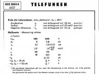
tfk 803S is a special quality tube, selected at source. Is not made any more.The datasheet from Telefunken gives limits for a good tube.
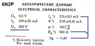
So does the sheet for the russian (almost equivalent 83) 6N2P.
Mona
6N2P is NOT ecc83.
Whoww, thanks a lot for all your excellent input!
The manufactor is JJ-electonics and they say only it´s "like" ECC83 but with long plates and "long life" version.
Aahh, you mean LINE 94 but it´s tube #92 Yes, this one an #4 and #20 have quite different systems...
I get a math like this to calculate a "sum" of Ia and mu:
1/4*(2*ABS(Ia1 - Ia2)/(Ia1 +Ia2) + 2*ABS(mu1 - mu2)/(mu1 + mu2) + [other parameters]...)
Not understand this but it was given from a math-expert to me..
regards
Karsten
The manufactor is JJ-electonics and they say only it´s "like" ECC83 but with long plates and "long life" version.
Aahh, you mean LINE 94 but it´s tube #92
Yes, this one an #4 and #20 have quite different systems...I get a math like this to calculate a "sum" of Ia and mu:
1/4*(2*ABS(Ia1 - Ia2)/(Ia1 +Ia2) + 2*ABS(mu1 - mu2)/(mu1 + mu2) + [other parameters]...)
Not understand this but it was given from a math-expert to me..
regards
Karsten
I'm wondering what's the purpose of this ?
Original Special Quality tubes like the ECC803S (ECC802S,EF806S,E80CC, etc...) were build to tighter electrical and mechanical tolerances and pre-aged (stabilized), they were rarely used in consumer audio equipment but intended for critical applications like metrology,medical,aerospace, industrial equipment, etc... where reliability was paramount and price a secondary factor. They were much more expensive and usually didn't needed any matching or selection, being already pre-tested/pre-aged/selected tubes.
The problem is that currently manufactured ECC803S are nothing more than rebranded common ECC83/12AX7s with a more luxurious packaging (and higher price) but don't have any of the refinements of the real Special Quality tubes made in the good old days. Also, they don't go through any pre-aging/stabilizing process. Then, the question is: after you have carefully matched your tubes by statistical analysis based on actual measurements HOW LONG will they remain matched once you'll put them into service. A couple of hours ? A few days ? And which parameter is the most important in your circuit ? I've never seen an audio equipment so far who requires critical close matching of the small signal tubes, or it must be a very poorly designed circuit.
> I simply add all values ( Ia,mu,Ra,Gm) of one system. Next I divide the sum of both systems. If the result is 1 both system matches exactly.
No, because a side could have high Ia and low Mu and give the same score as the other side. Imagine a tube half 12AX7 and half 12AU7.
And as Ra and Mu are larger numbers than Ik and Gm they count for more.
But back up. You have tested at "fixed" bias. Do we ever run preamp tubes in fix bias? No! And one reason is that they vary so much! But if we use self bias (significant cathode *and* plate resistors), the hot units down-bias and the cool units up-bias.
Take tube #26:
Ia 0.99,1.31 (1.32 ratio)
Gm 1.45,1.61 (1.11 ratio)
Significant difference in Ia at same bias *voltages*. About a 1.32 ratio. But put 1.5K under and 100K above it, the difference will be around half. Or perhaps square-root. Now more like 1.15 ratio of Ia. Gm will fall with Ia, and roughly as root of Ia. I predict these two units match in-circuit within 4%.
In small-signal work it probably makes much more sense to "match" audio gain in a typical circuit. For 12AX7 types, 1.5k and 100K with a 220K audio load. Feed 0.1V in, and look for 5V out. Anything outside 4.5V (dud) or 5.5V (unlikely) goes to the guitarists' sale.
With no cathode bypass, more like 2.5V out and much lower variations. 1.5K spoils-down Gm, and levers-up Rp, the same on all tubes, reducing the differences.
If you need better than 5%-10% gain accuracy, Harold Black nailed it: make way too much gain and use NFB to make final gain a function of two stable passive parts.
Dear PRR,
Thanks a lot for your explanation! You are totaly right; the best thing is to test the tubes in circuit, for sure. Instead to measure static values it makes sense do select the tubes within a small test circuit which has the same design as the target.
This is the result of this nice and very educational thread for me. And I´m very thankful for all your time and help!
My first aim was to get dedicated and reliable measurments to be able to sort out and pair tubes. Tubes which are to far away from given data by manufactor should be send back. And to do this I have to provide hard facts; I think JJ-electronics will not accept a return shipment if I say "They don´t fit my personal idea of tube quality".
So over all, I will build my own "In circuit" tester. Tubes wich are not fit my requirements, must then be tested again with uTracer to retrieve "hard facts".
The other way is to buy pre selected tubes from manufactor. But... They don´t tell me the tolerance about thier selection. All information I get ( until now ) is that they select by Ia.
By the way why modern ECC803S. For my realy subjective and personal opine this tube works excellent. And I´m not a beliver of that everything was better,higher,nicer... concerning tubes in old days. Espacial NOS tubes which sometimes hard to get and high price for a not know condition... Sorry, this is totaly Off-Topic....
So: Thank you all for your great input and I have to say: Its every time a big pleasure to be here: So much friendly and wise guys!!!
Best regards
Karsten
The original Tfk ECC803S used a frame-grid construction. They also had a conventional ECC83. Then Tesla did a frame-grid ECC83 and a conventional ECC803S (just to avoid confusion). The modern JJ ECC803S has a frame-grid-like anode structure but might not actually have a frame grid - the JJ blurb seems to be deliberately vague on this.
Yes, this is the advantage of traditional resistor bias and loading - it reduces variation, between samples and due to ageing. Those using CCS (or fixed voltage) bias or loading have to accept wider variation in whatever they are not fixing.PRR said:Significant difference in Ia at same bias *voltages*. About a 1.32 ratio. But put 1.5K under and 100K above it, the difference will be around half. Or perhaps square-root. Now more like 1.15 ratio of Ia. Gm will fall with Ia, and roughly as root of Ia. I predict these two units match in-circuit within 4%.
A couple of follow on comments: because mu is derived from rp and gm, it's not an independent variable. Second, you might want a weighting factor since order of magnitude of rp and mu is 100, order of magnitude of Ia and gm is 1- if you take any row there and set Ia to zero, you'll see that your system derivation factor barely moves.
> because mu is derived from rp and gm, it's not an independent variable.
A different, maybe insightful, way to see it:
Mu is a *geometrical* parameter. Mu may be calculated if you know the internal dimensions exactly. Grid wire diameter and spacing, grid-cathode-plate spacings.
That's not Absolute Truth in real tubes. Mu always drops at low current, because the main high-Mu part of the tube cuts-off, leaving sneak-paths of lower Mu around the ends of the non-infinite grid. Mu often appears to fall at high current, perhaps due to grid "filling with electrons", but also because many tube testers run large grid signals and run into grid current which may reduce effective drive and certainly diverts cathode current. Many older tubes have very "flat" Mu curves. Many of the hotter tubes from the modern era (1950s) are goosed-up at high current and show more Mu slope. (Variable-Mu tubes make the sneak-paths a major part of the useful operating range.)
Gm is how well the cathode emits and how well the grid winding controls it. The absolute limit is proportional to current the same as a BJT. No real tube comes close because the finest grid wires are far too fat (we need crystal-size grid structures, which is why a BJT gets close to the Gm/Ie limit). Gm is set by cathode activity and grid dimensions.
The Rp is the "independent" variable, being essentially Mu/Gm. If you know Mu and Gm there is no need to measure or note Rp. Just derive it when you do circuit computations.
No. In an ideal fixed-mu triode valve gm is proportional to the cube root of current. Only in an ideal variable-mu (remote cutoff) valve is gm proportional to current, like a BJT.PRR said:The absolute limit is proportional to current the same as a BJT. No real tube comes close because the finest grid wires are far too fat (we need crystal-size grid structures, which is why a BJT gets close to the Gm/Ie limit).
Not really. Given any two (whether from measurement, theory or simulation), you can calculate the third.The Rp is the "independent" variable, being essentially Mu/Gm.
I would say that any testing of tubes ( to compare with documented values) should be done
at the same working points as the document.
And all (?) ecc83/12ax7 vendors specify typical characteristics at Va=250V and Vg=-2
( it also specifies Va=100 and Vg-1 but that is less typical in applications)
Measuring at any other points will make it difficult to relate to ECC83
( well comparing anode curves would also do but that is more complex then a go-nogo
evaluation)
- Status
- This old topic is closed. If you want to reopen this topic, contact a moderator using the "Report Post" button.
- Home
- Amplifiers
- Tubes / Valves
- Matching 100 tubes ECC803S