I decided to delve back into the valve amplifier era inspired by my 16 year-old son who is becoming a bit of an audiophile and showed an interest in valves.
In my youth (about 14) I messed around with broken valve TVs from the local scrap yard (they had a removal van full of them!), swapping the ones with white tops for silver ones and getting them to work. As a result I had biscuit tins full of EF86, ECC83, PL508 etc. plus acquired various radio valves from those huge radiograms that adorned peoples houses.
Then, with the advent of transitorised TVs and Japanese Hi-Fi I gave them all away...
So, browsing various online sites I came across a reasobably priced and spec'd offering: Douk Audio EL34B Class A Single-ended Tube Amplifier HiFi 2.0 Channel Power Amp. Rated at 12x2W ultra-linear connection the amplifier is designated A10, has 6N2J×2/EL34B×2/5Z4PJ×1 and is the 'uprated' version with 76x40 output transformer compared with 'old' 66*50.
I know there are a few posts about this design/manufacture of amplifier already, however they are a couple of years old so thought it would be worth an update.
The amplifier was shipped from Germany (it was cheaper than buying the same model from their UK warehouse) and arrived incredibly well packed, being double-boxed and secured by custom made polyethylene foam. Valves seperately packed in the same box (slight panic as only four boxes but found the two small valves in one box).
Having carefully unpacked all items and found no damage, I plugged in the valves, connected my Mission 760i SE 8-Ohm speakers (they have had very little use since I bought them several years ago due to my other main speakers), checked volume low and switched on. No bangs, no sparks no pops... Good! Waited a full minute, connected iPhone via 3.5mm to twin RCA phono connections on the rear, selected some music and turned up the volume.
I must admit to being very impressed: A great punchy bass, clear highs and if I had any criticism maybe the mid was a little 'glassy'. The amp. has been running for about 40 hours already now as I have also connected the TV output via the same 3.5mm jack. As the output of the TV jack can presumably go over the 1v p/p I was careful in turning the TV volume up, but the amp behaves very well with little perceivable distortion.
In the spirit of experimentation, I have purchased two Russian Military 6N2J-EV and substituted those, which came with rubber rings. I can't really say I have noticed any difference. The stock supplied EL34B is a Shuguang so I'm not planning to change them in the short term, although I have seen suggestions to change them to KT77 as straight plug-in.
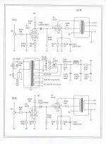
Attached is the circuit diagram which they have kindly supplied for the express purpose of modification. The next easy possibility is to change the stock supplied 5Z4PJ for a GZ34 as I have seen that suggestion elsewhere.
In future, I like the idea of a regulator for the bias circuit.
This weekend I will take some photos of the unit itself, exterior and interior (which I've not seen yet...)
In summary, my experience is very positive and I am very happy with the purchase - time will tell of course.
Any suggestions or comments on upgrading / improving welcomed.
In my youth (about 14) I messed around with broken valve TVs from the local scrap yard (they had a removal van full of them!), swapping the ones with white tops for silver ones and getting them to work. As a result I had biscuit tins full of EF86, ECC83, PL508 etc. plus acquired various radio valves from those huge radiograms that adorned peoples houses.
Then, with the advent of transitorised TVs and Japanese Hi-Fi I gave them all away...
So, browsing various online sites I came across a reasobably priced and spec'd offering: Douk Audio EL34B Class A Single-ended Tube Amplifier HiFi 2.0 Channel Power Amp. Rated at 12x2W ultra-linear connection the amplifier is designated A10, has 6N2J×2/EL34B×2/5Z4PJ×1 and is the 'uprated' version with 76x40 output transformer compared with 'old' 66*50.
I know there are a few posts about this design/manufacture of amplifier already, however they are a couple of years old so thought it would be worth an update.
The amplifier was shipped from Germany (it was cheaper than buying the same model from their UK warehouse) and arrived incredibly well packed, being double-boxed and secured by custom made polyethylene foam. Valves seperately packed in the same box (slight panic as only four boxes but found the two small valves in one box).
Having carefully unpacked all items and found no damage, I plugged in the valves, connected my Mission 760i SE 8-Ohm speakers (they have had very little use since I bought them several years ago due to my other main speakers), checked volume low and switched on. No bangs, no sparks no pops... Good! Waited a full minute, connected iPhone via 3.5mm to twin RCA phono connections on the rear, selected some music and turned up the volume.
I must admit to being very impressed: A great punchy bass, clear highs and if I had any criticism maybe the mid was a little 'glassy'. The amp. has been running for about 40 hours already now as I have also connected the TV output via the same 3.5mm jack. As the output of the TV jack can presumably go over the 1v p/p I was careful in turning the TV volume up, but the amp behaves very well with little perceivable distortion.
In the spirit of experimentation, I have purchased two Russian Military 6N2J-EV and substituted those, which came with rubber rings. I can't really say I have noticed any difference. The stock supplied EL34B is a Shuguang so I'm not planning to change them in the short term, although I have seen suggestions to change them to KT77 as straight plug-in.
Attached is the circuit diagram which they have kindly supplied for the express purpose of modification. The next easy possibility is to change the stock supplied 5Z4PJ for a GZ34 as I have seen that suggestion elsewhere.
In future, I like the idea of a regulator for the bias circuit.
This weekend I will take some photos of the unit itself, exterior and interior (which I've not seen yet...)
In summary, my experience is very positive and I am very happy with the purchase - time will tell of course.
Any suggestions or comments on upgrading / improving welcomed.
Attachments
If you regulate the bias supply you must regulate the HT. If the HT rises the -ve grid bias must increase as the valve will draw more current if not and change the class more to overload from class A and vary the output sound. The bias circuit in your schematic is a 500R resistor so not an easy task to regulate.
Try and get some Russian 'Winged C' EL34s if you can. Slightly more reliable. The Audio Innovations amplifiers had lots of problems with Chinese EL34s.
Try and get some Russian 'Winged C' EL34s if you can. Slightly more reliable. The Audio Innovations amplifiers had lots of problems with Chinese EL34s.
Hi JonSnell - thanks for your comments...
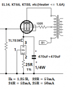
The bias circuit 'tip' I picked up from Ygg-it on this site where he has made a huge number of mods to his A10. His mod. is for constant current source for the bias (see attached circuit) and he doesn't have a mod. for the HT. I don't know if that makes a difference to your statement?
The bias circuit 'tip' I picked up from Ygg-it on this site where he has made a huge number of mods to his A10. His mod. is for constant current source for the bias (see attached circuit) and he doesn't have a mod. for the HT. I don't know if that makes a difference to your statement?
Attachments
Doing it with a constant current load is ideal. HT rises and the load will compensate. I read your article as if we supply the control grid with a constant voltage that is divorced from voltage changes. Most manufacturers get that extra ounce out of the output valve by grounding the cathode and providing a negative voltage to the control grid. That adds an extra 30 volts or so to the useable voltage swing. If the negative voltage is sourced from the mains transformer without regulation, the bias tracks perfectly. If it is regulated, there is no tracking so the valve can change class from AB1 to A and even to over current, damaging the valve.
I am not good at explaining myself.
I am not good at explaining myself.
A minor problem with cathode CCS bias is that it stabilises the wrong thing: average current instead of quiescent current. In this respect it is actually worse than a simple resistor! As a result in order to avoid too much distortion on big signals you have to bias the valve 'hotter' for small signals (and no signals). Not a huge problem, as a UL-connected SE pentode with no overall feedback will not give low distortion anyway.
Looking through various posts in various places, I came across this:
"Here are some old notes on CCS ( Constant Current Sources )
http://www.siteswithstyle.com/VoltSecond/CCS_college/CCS_College.html
Where to use the CCS?
I don't see the need to CCS the grid of a tube nor do I recommend it.
On single ended designs, you CCS where the "ac" energy is coming out. On a cathode follower, you CCS the cathode. On a stage with plate output, you CCS the plate.
On push-pull designs, you can CCS the cathode of the "long tail pair" or where the cathodes of a stage are tied together.
http://www.siteswithstyle.com/VoltSecond/K-12M_AMP/K-12M_Push_Pull.html
On triodes, only CCS one pin. The other pin normally will need to go to an "ac ground" An "AC" ground is ground or a capacitor going to ground. It is called an "ac" ground because at "ac", it is attached to ground.
On a Pentode, you can also have a CCS fed shunt regulator on the screen.
On push-pull designs, you can CCS the cathode of the "long tail pair" or where the cathodes of a stage are tied together."
Now, I'm keen to experiment as long as there is a 'real' purpose and discernible outcome, so if anyone has actually implimented any of the above and can comment on their experience I will be really grateful")
Many thanks in advance.
"Here are some old notes on CCS ( Constant Current Sources )
http://www.siteswithstyle.com/VoltSecond/CCS_college/CCS_College.html
Where to use the CCS?
I don't see the need to CCS the grid of a tube nor do I recommend it.
On single ended designs, you CCS where the "ac" energy is coming out. On a cathode follower, you CCS the cathode. On a stage with plate output, you CCS the plate.
On push-pull designs, you can CCS the cathode of the "long tail pair" or where the cathodes of a stage are tied together.
http://www.siteswithstyle.com/VoltSecond/K-12M_AMP/K-12M_Push_Pull.html
On triodes, only CCS one pin. The other pin normally will need to go to an "ac ground" An "AC" ground is ground or a capacitor going to ground. It is called an "ac" ground because at "ac", it is attached to ground.
On a Pentode, you can also have a CCS fed shunt regulator on the screen.
On push-pull designs, you can CCS the cathode of the "long tail pair" or where the cathodes of a stage are tied together."
Now, I'm keen to experiment as long as there is a 'real' purpose and discernible outcome, so if anyone has actually implimented any of the above and can comment on their experience I will be really grateful
Many thanks in advance.
A few years ago someone made a PCB which samples the current at the input signal zero crossing, thus sensing the quiescent current and adjsuting the grid bias accordingly. In my opinion, not worth doing for this simple circuit as the existing cathode resistor is good enough.Mission720 said:So is there a modification which would stabilise the quiescent current rather than average current?
The only way to improve this circuit is to add more gain and add negative feedback. You might then find that the OPT is not good enough to cope with this. Better then to start again with a better circuit using push-pull.
Now, I'm keen to experiment as long as there is a 'real' purpose and discernible outcome, so if anyone has actually implimented any of the above and can comment on their experience I will be really grateful
All of the above. In all cases replacing a resistor with a CCS resulted in improved sound. Also, not all CCSs are created equal. Differences can be readily heard. My main system that I listen to consists of LTPs with CCS "tails" and individual CCS fed shunt regulators for each stage. Most of the sonic gains that I have achieved over the years with this system have come from changing the CCSs. This has also been my experience with plate loads used in single ended stages.
If you want to try this for yourself K&K Audio sells small CCS kits that are very convenient to use. Measure the voltage drop across cathode resistor of the input stage and calculate the current. Set the CCS to that current and replace the plate load resistor. That easy.
The only way to improve this circuit is to add more gain and add negative feedback.
Spoken like a true engineer. BTW you'd hate my system. It's all transformer or direct coupled. From the phono inputs I count eight transformers in the signal path. You are right about one thing. Good transformers are expensive. Lundahl amorphous C cores aren't cheap. ;~)
- Status
- This old topic is closed. If you want to reopen this topic, contact a moderator using the "Report Post" button.
- Home
- Amplifiers
- Tubes / Valves
- Chinese EL34B SE "A10" Disection