Hi Guys,
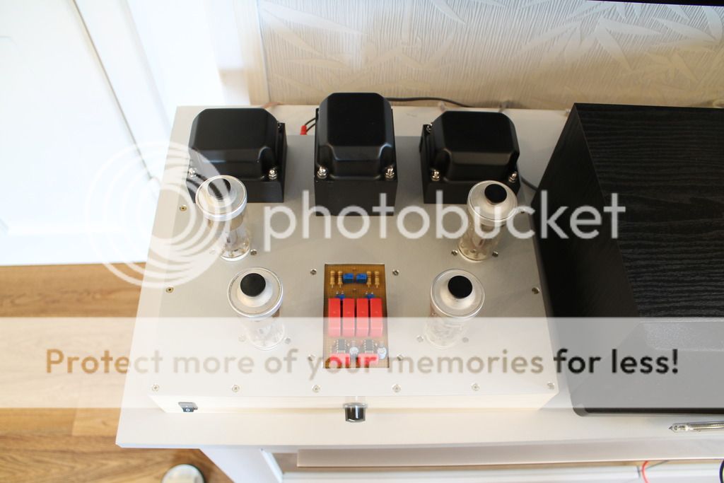
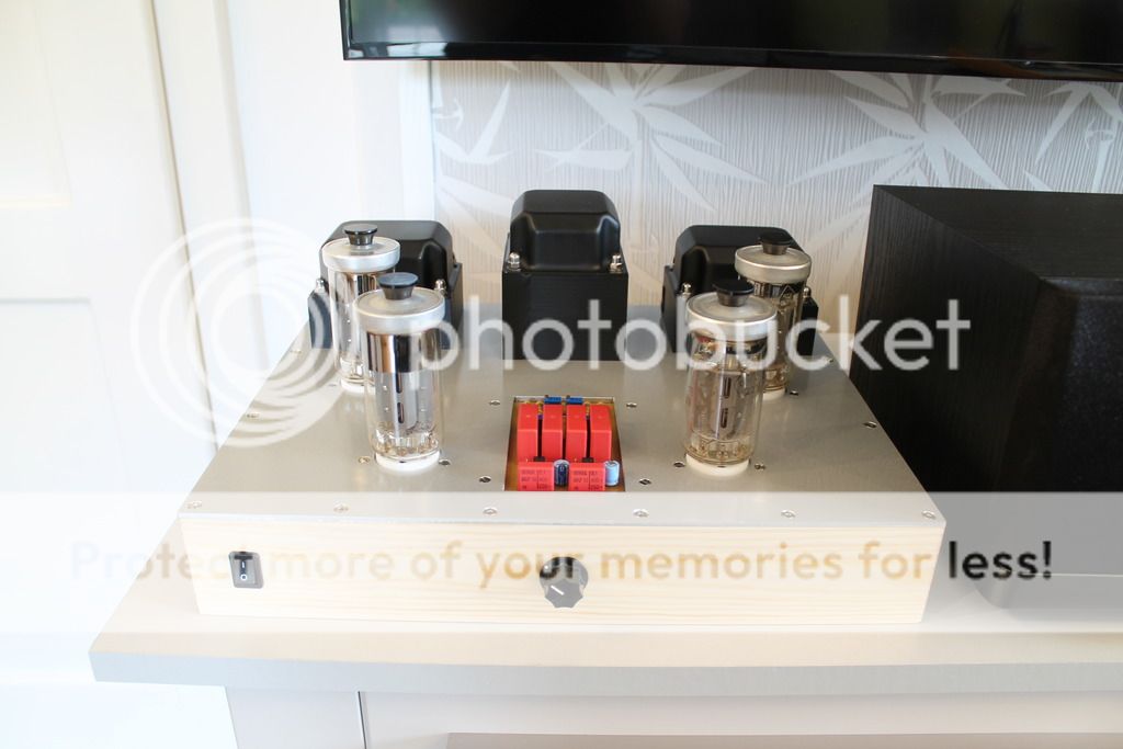
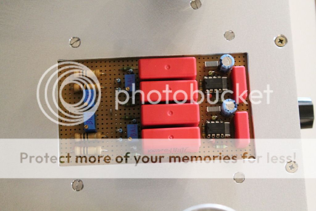
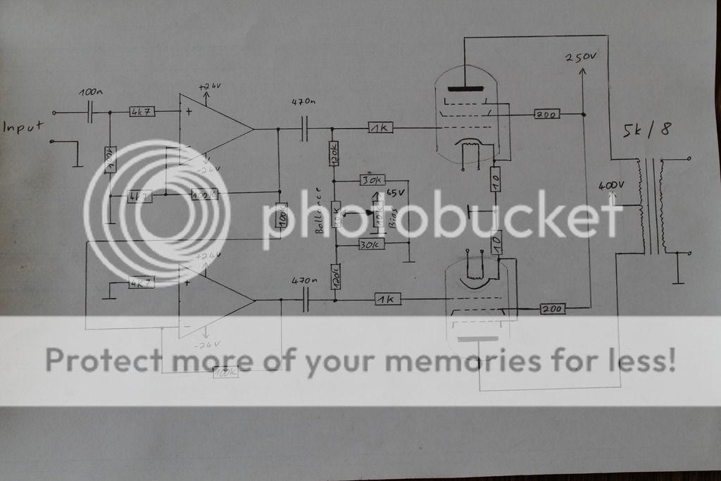
I built a tube amp with GU-50 and solid state driver. My first homemade tube amp") I used this circuit for the driver: Valve Amps: Pre-amp and Driver
I used this circuit for the driver: Valve Amps: Pre-amp and Driver
At the end of the link.
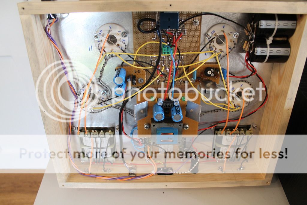
The tubes are wired as pentodes. Grid 2 Voltage 250V, anode voltage 400V, 50mA per tube. My output transformers have 5k.
Erything works but there is way too much treble and the heights are distorted...
Do you have some ideas that could fix this problem?
Maybe some kind of negative feedback?
some pics:
Regards, Daniel
I built a tube amp with GU-50 and solid state driver. My first homemade tube amp
I used this circuit for the driver: Valve Amps: Pre-amp and DriverAt the end of the link.
The tubes are wired as pentodes. Grid 2 Voltage 250V, anode voltage 400V, 50mA per tube. My output transformers have 5k.
Erything works but there is way too much treble and the heights are distorted...
Do you have some ideas that could fix this problem?
Maybe some kind of negative feedback?
some pics:


Regards, Daniel
Without complete schematic, it's rather difficult to help.
I hope you don't mind but i'm just posting because i'm curious about your op-amp driver circuit
I don't see how the typical op-amp can swing the full voltage needed to clip the GU50.. Va = 400V, Vg2 = 250V and Ia = 50mA translates to Vg1 around -35V. Must be some expensive high voltage op-amp you got there, especially since i don't see any bootstrap circuit around.
Like i said the schematic of the solid state driver is in the link.
The output tubes are connected like this: http://www.jogis-roehrenbude.de/Leserbriefe/Peter-Schippmannns-GU50-Amp/GU50Amp.gif
except of the negative feedback.
No high voltage OP-AMP, not expensive... 5€ per pcs.
+-24V supply - far enough for clipping.
GU-50 ≈ EL152
The data sheet of EL152 says 20V ~ on G1 is enough for ~50W and it is enough believe me
Datasheet EL152 (german):
http://www.mif.pg.gda.pl/homepages/frank/sheets/118/e/EL152.pdf
page 9 "Betriebswerte für NF Endverstärkung"
So do you have an idea how to solve the problem?
Yes, i got you the first time. However, Lenard clearly said it's "discretely made high Voltage op-amps".. so, it's not your regular cheap op-amp (with its limited swing).Like i said the schematic of the solid state driver is in the link.
The data sheet of EL152 says 20V ~ on G1 is enough for ~50W and it is enough believe me
It's 20Vrms, not 20Vpeak. 20Vrms = 28Vpeak which is exactly where Vg1 is biased at (Gittervorspannung Ug1), so you're not clipping the output tube with your op-amp driver (and you're not reaching 50W).. but i don't doubt it's loud enough even with only 20V swing.
But, anyway, that's irrelevant to your problem. Without seeing the full schematic (it's the small details that's sometimes the problem), i see three possible issues:
1. Too small coupling capacitor value (from the op-amp driver to GU50 grid). This is unlikely but i thought i should state this.
2. Poor quality output transformer
3. Your speaker doesn't like low damping factor, which is what you get from pentode connection. Notice how Lennard shows the output tube connected as ultra linear in your op-amp/solid state driver schematic. Ultra linear connection will increase damping factor and in most cases, improve the sound. He explains this clearly on the solidstate vs valve link (Valve Amps: Valve verses Solid-state amps).
.
If your problem is #3, there's a major rework to be done to allow ultra linear to be introduced in your circuit, especially since Vg2 is much lower than Va. Here's one way to do it: Audio Asylum Thread Printer
No high voltage OP-AMP, not expensive... 5€ per pcs.
+-24V supply - far enough for clipping.
Have you actually measured your negative grid bias and made sure it is less than -24V?
I'm actually designing an op-amp based input stage for tube amps and am using the ADA4700 with +-48V supplies. I did things differently. I made it more like the input stage of an instrumentation amp. It is meant to be fed from a balanced source.
Thanks for the answer.
1. i have 100nF for the OP-AMP input and 470nF for the G1 input.
2. i hope not...
3. could that be done with negative feedback...?
I can adjust the g2 voltage to any value between 100 and 400V if necessary.
@ Spread Spectrum: I decreased the anode current to 35mA. I have about -40V G1 now.
1. i have 100nF for the OP-AMP input and 470nF for the G1 input.
2. i hope not...
3. could that be done with negative feedback...?
I can adjust the g2 voltage to any value between 100 and 400V if necessary.
@ Spread Spectrum: I decreased the anode current to 35mA. I have about -40V G1 now.
Could that be done with negative feedback...?
Ultra linear IS a form of negative feedback. It's one way to wrap local feedback around the output tube. Local feedback is your only option as the op-amp driver won't allow any global negative feedback.
I can adjust the g2 voltage to any value between 100 and 400V if necessary
In that case, you can try triode connecting the output. Disconnect G2 from your 250v supply and connect it to the plate, put 100-470R resistor in between. Adjust Vg1 accordingly to avoid excessive plate current.
Yes, I think the omission of feedback is the main problem....
3. could that be done with negative feedback...?
If you are driving the amp with a low impedance source, and since the amplifier is inverting, you can incorporate negative feedback by adding a 10k input resistor between the 100nF cap and the op amp input and a 470k feedback resistor from speaker terminal to the input resistor + op amp input connection.
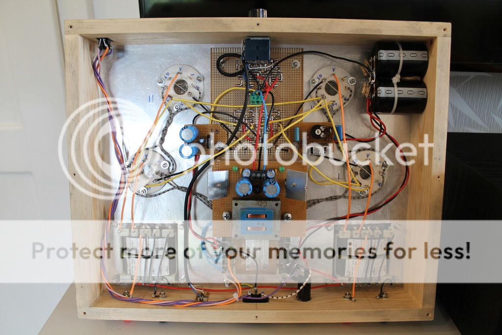
It appears that you have either omitted the G1 and G2 stopper resistors or else located them incorrectly. They belong at the tube socket contacts with near-zero lead length. Spurious oscillation and therefore audio distortion is likely if that's not done correctly.
The input stage op-amp is non-inverting, despite the wave relationship drawn by Lenard Audio. Feedback must go to its inverting input if you keep the existing arrangements.
It's really too bad that you didn't breadboard this amp before construction, because your build quality looks quite good. Is there any chance that you have access to a scope and audio signal generator?
Hi.
Thanks for the replies.
@BinaryMike: I had the G2 resistor directly at the socket but the G1 resistor was about 10cm away from the tube - i changed that, now it is on the socket. Thanks.
Yes i have an oscilloscope and and function generator.
Since the feedback would be easy to implement i want to try that first.
I have drawn the schematic:
With Feedback:
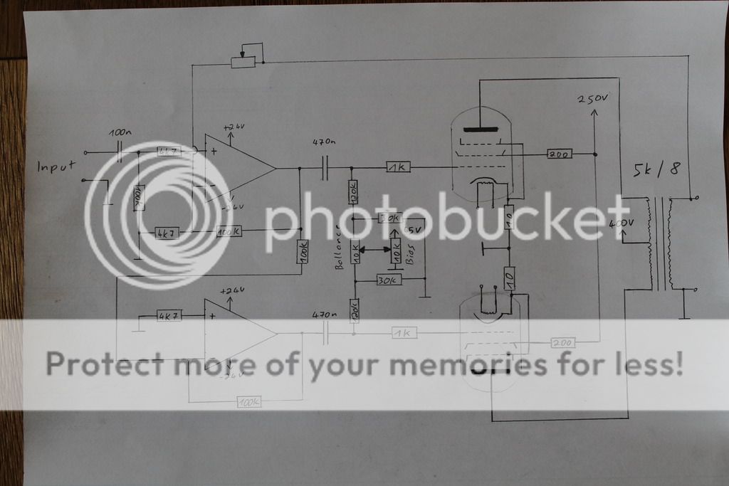
Is that right...? I just noticed i forgot a "safety" resistor in series with the feedback potentiometer.
Thanks for the replies.
@BinaryMike: I had the G2 resistor directly at the socket but the G1 resistor was about 10cm away from the tube - i changed that, now it is on the socket. Thanks.
You are right... But it is not yet lost!It's really too bad that you didn't breadboard this amp before construction, because your build quality looks quite good.
Yes i have an oscilloscope and and function generator.
Since the feedback would be easy to implement i want to try that first.
I have drawn the schematic:

With Feedback:

Is that right...? I just noticed i forgot a "safety" resistor in series with the feedback potentiometer.
Last edited:
Your feedback scheme should be okay, but keep in mind that you might have to swap phase at the OPT (or G1 connections) if you get oscillation.
The finals can never reach full output with grid bias at -40V because your op-amp outputs clip at 22~23V. SpreadSpectrum suggested using the ADA4700 on +/-48V supplies, which could be a good solution. Input stage gain is about 20 as drawn, but needs to be around 400 to achieve 20dB feedback. That's a lot of gain even for a good audio op-amp. It should be split into two stages. I think you're missing a great opportunity for direct grid drive, but the additional complexity might be unwelcome at this point.
The finals can never reach full output with grid bias at -40V because your op-amp outputs clip at 22~23V. SpreadSpectrum suggested using the ADA4700 on +/-48V supplies, which could be a good solution. Input stage gain is about 20 as drawn, but needs to be around 400 to achieve 20dB feedback. That's a lot of gain even for a good audio op-amp. It should be split into two stages. I think you're missing a great opportunity for direct grid drive, but the additional complexity might be unwelcome at this point.
Last edited:
The input stage op-amp is non-inverting, despite the wave relationship drawn by Lenard Audio. Feedback must go to its inverting input if you keep the existing arrangements.
no, feedback can go to either input, because you can always swap ground and feedback pickup at the speaker output to make it negative fb ...
what you hear as distortion is the typical tube sound - of a pentode; pentode outputs require negative fb.
Lenard's uses ultralinear taps on the output txfmr to implement local feedback just to the output stage; if you don't have these taps on your txfrmr, you need global feedback across all stages;
however, the open-loop gain of the OP's design is way too low to successfully accomodate any global negative fb :
look at jogi's design: there are 2 gain stages:
- Rö1 as connected gives gain of 40x
- Rö2 gives gain of 25x
- GU50 have gain of approx. 4x when working into txfmr + speaker load
- but txfmr has 10:1 ratio or so, so attenuates 0.1x
------> total open loop gain in jogi's is therefore (40x25x4)/10=400 (actually 800 because of push-pull)
simplified said, negative fb trades gain for distortion; a very crude statement would be to say: if you want 1/10 the distortion, you have to spend 10x the available open-loop gain.
jogi can do that because he has 800x available and he needs just 10x or so, he spends 80x of gain to get rid of pentode distortion.
your design has 21x in the OP stage, 4x outputs, 0.1x txfrmr, which gives you open loop gain of (21x4x0.1)=8.4 (actually 16.8 because of pp)
---> you have no gain reserve to trade in ....
so - you either find those UL taps on your txfrmr (many have) then your setup can be saved, or you have to implement far more gain.
Adding gain upstream of the existing op-amp driver doesn't solve the problem of premature clipping. It could supply the extra gain needed for a generous amount of feedback, however. My own solution to this problem was to insert a high-voltage 'op-amp' driver stage made with discrete transistors, between the input op-amp/inverter circuit and the power tube grids. Here's how I did it: https://dl.dropboxusercontent.com/u/57580004/Perveant Breadboard.pdf
Hi.
Thanks for the answers!
Hmmm unfortunately the OPTs have no UL taps...
So what would you guys recommend me to do...?
Should i try to use the ADA4700 OP-AMPs on +-48V with global negative feedback or should i use a tube pre stage instead?
Regards, Daniel
If you cannot go UL, you need all three:
- global negative fb to get rid of the pentode's distortions
- much more gain for gnfb to work properly
- more voltage swing to drive the GU50s to the desired power level
BinaryMike shows that it can be done with semiconductors but is not simple and requires design skills and possibly spice simulation ...
speaking of simulation, it would allow you to play with modifications like fb and try out possible solutions on your computer, highly recommended ... LTSPICE is free sw.
Of course you could go entirely with jogi's design - all tubes - and throw out those op-amps; jogi's design will work for shure; the 4 tubes are all 12v/0.15a heaters and could be run from the same 12v as the GU50s if your mains txfmr has headroom for 0.6a more heater current; you could fit them on a PCB to replace the one with the red caps in the middle.
And of course you can try your simple fb scheme just for the fun of it (not indra1's it will not help) and find out by yourself; it will not do any harm but prediction is that if you adjust the pot for little fb it will not help the sound and if adjusted to more fb you will not get much output unless you feed the amp from a preamp with 10v output.
By the way, be careful with these chinese GU50 sockets you have if you unplug and re-insert the tubes; they have a reputation of damaging the tubes, and I can confirm that by my own experience.
The point is that the socket springs have too much space to move, so it is easily possible to insert the tube such that a pin misses the center of a spring and is caught beween spring and sidewall of the hole in the ceramic; when pushing the tube down into the socket this pin experiences a mechnical stress sideways which almost inevitably causes a crack in the all-glass base of the GU50.
In my case my first GU50 worked until the day after when enough gas had leaked into the envelope to turn it into a big glow tube.
So make shure that all 8 pins hit the center of their respective contact spring before pushing the tube down ...
I thought it would be simple driving the GU-50s with solid state drivers and get a good result... But it is not. Alright then i think i will use this circuit instead of the solid state driver:
Gegentakt-Verstärker in AB-Betrieb fuer GU 50
I have some russian 6N8S at hand - 6SN7 equivalent. They have a 6,3V heater. 2 heaters in series connection should work on 12,6V without any problems right? The transformer should also handle the additional heater current, it is made for 12,6V @ 4A. One GU-50 requires about 0,8A or less.
Yes those Chinese sockets are not well designed... Would not buy them again.

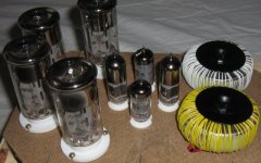
Installed some socktes for the new tube prestage:

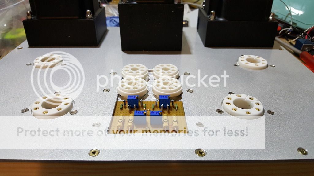
A bit tight but it fits! And i think it looks even better than before.
I will use this circuit with 6H8C tubes:
http://www.jogis-roehrenbude.de/Verstaerker/GU50-Grommes/Schaltung.gif


A bit tight but it fits!
And i think it looks even better than before.I will use this circuit with 6H8C tubes:
http://www.jogis-roehrenbude.de/Verstaerker/GU50-Grommes/Schaltung.gif
- Status
- This old topic is closed. If you want to reopen this topic, contact a moderator using the "Report Post" button.
- Home
- Amplifiers
- Tubes / Valves
- GU-50 + solid state driver