Hi there,
Moderators, I am not sure this is considered as a tube question or just a PS question, feel free to move it to the power supply threads if it is more appropriate there.
Background, I am trying to restoring an Eico 950B bridge (manual attached).
I have replaced the old caps and resistors, and the 6x5 and the 1629 are both checked out good and strong.
The problem that I have is that I can't get the voltage to reach 500V in the electrolytic leakage setting. I only get 470VDC at max. I did some measurements,
= The HV secondary is around 575VAC and it is never below 560VAC during the day. It is higher than what the manual specified. So, not like a problem with the transformer.
= Pin 8 is at 199VDC, reference to ground, so very close to the 200VDC mark.
= From C1 neg to ground is only -480, not -520. That kind of explains why I couldn't get 500V.
In the manual's circuit description section, it says:
... the negative dc required for leakage testing of capacitors are obtained from 6x5 tube connected as half-wave rectifier, in conjunction with the high voltage secondary winding of the power transformer and the filter and the voltage divider networks composed of R8, R7, C1, and C9.
My question is, how does this circuit work to get to the desired -520?
FWIW, I used 2 20uF cap connected in series to replace C1, and 4.7uF to replace C9, not sure the different values is the cause or not, but it is worth to mention upfront for the kind helpers.
Thanks!!
Attachments
Might be worth checking that the pot P3 hasn't gone low in value. Just a thought.
How does it work.... it appears to be just a half wave rectifier generating 720 volts across the two series caps. R8 makes analysing it a bit more tricky because I think the voltage across R8 is going to depend on the current drawn by the magic eye.
How does it work.... it appears to be just a half wave rectifier generating 720 volts across the two series caps. R8 makes analysing it a bit more tricky because I think the voltage across R8 is going to depend on the current drawn by the magic eye.
If you didn't use equalizing resistors across the new 20uF caps at C1, there's a good chance that you now have a serious leakage problem there. And if you DO use equalizing resistors, they need to be high enough in value to avoid dragging the voltage down. Check the capacitor leakage specs to be sure.
Hi Mooly,
I also suspect P3 being bad and forgot to mention that I measured it out of circuit and found it was open!! To be more specific, I found broken wound wire at the ground side. I was wondering how the ground was referenced as the circuit was semi-working for the longest time.
These days, it is very difficult to find such pot (100K/4W) without costing an arm or a leg, so I probably will continue to use it to reform and to check leakage of the older caps. The reason for the question is really to try to learn how this circuit generates 720VDC when all parts are working properly.
Thanks for the help!!
If you didn't use equalizing resistors across the new 20uF caps at C1, there's a good chance that you now have a serious leakage problem there. And if you DO use equalizing resistors, they need to be high enough in value to avoid dragging the voltage down. Check the capacitor leakage specs to be sure.
OK, I will add 2 x 2M resistors which should not load down the voltage too much.
Thanks!!
-fredv-
The reason for the question is really to try to learn how this circuit generates 720VDC when all parts are working properly.
Mooly touched on that point, but maybe you need more information... The AC voltage sinewave peaks at 1.414 times its RMS (heating) value, which is 792V for the nominal 560VAC winding. Some of that is lost to the forward voltage drop of the rectifier tube, which is a function of peak capacitor charging current. Is that what you wanted to know?
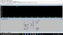
If I understand correctly, the circuit is a half wave rectification using the 6x5 tube with a 560VAC secondary. The ground of the circuit is simply a virtual ground created by a voltage divider from the +/- posts of the the caps after the rectifier. The voltage divider creates a +200 and a -520 rails with respect to the virtual ground. I suppose the voltage divider is formed by R8 (68K), R7 (3,3K), and P3 (100K), correct?
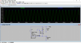
The problem is that, I wasn't able to get 720 VDC by measurement, not even close. I also modeled the above interpretation in PSUD2 and was not able to get 720VDC either. I wonder my understanding of the circuit is correct or not? The drop from the forward voltage of the 6x5 seems to be high in my observation, I wonder there are leakage somewhere is loading down the voltage. Any hint what to try out?
PS, I repaired the pot (P3). It is no longer open. Instead of 100K, it is measured 98K.
Thanks,
One thought. If the rectifier is suspect (not proven good by substitution) then how about adding a 'helper' silicon diode plus series resistor in parallel to the valve to bring the voltage up.
I guessed at the magic eye current and reduced the AC input to account for the forward volt drop of the rectifier just to prove it all works as we think.
I guessed at the magic eye current and reduced the AC input to account for the forward volt drop of the rectifier just to prove it all works as we think.
Attachments
IN4007 might not cut it as its going to see around 1kv+ in total. Two in series plus the resistor perhaps, at least as a trial. You really need something with a P.I.V. (peak inverse voltage) of around 1500v plus. Old TV flyback diodes could be a cheap possibility.
Attachments
First, I would like to thank BinaryMike and Mooly for all the help.
I think I got to the bottom of it finally; however, not the conclusion that I wanted")
I got in touch with another hobbyist who restores this kind of equipments namely, Eico, Heathkit, Paco, Knight etc.
First he told me was that there was no way I could get 720VDC from 560VAC!!! However, it is possible to get 720VDC or higher with the main from today.
Second, the load of this CR bridge is actually relatively low; therefore, there can only be a few possibilities not to reach 720:
- excessive leakage somewhere
- tired tubes
- transformer
I ruled out the 1st too by measurement and tube replacement, then it could only be the transformer. I measured the DCR and found it was close to 20% higher!!! The typical DCR should be around 1630R, but mine is at 2030R. So, the PT is loading down the secondary!!!
I found a couple simple tricks that I could get to 500VDC without too much changes if the main cooperates.
1. Fine tune R8 (68K) to lower the B+ to something like 190. This wouldn't affect the leakage test. This shifts another 5-10VDC to the neg end.
2. Jumper or lower R7 (3.3K) will provide up to 15 or so VDC to the P3 on the neg side.
At the end, I learned a few tricks on trouble shooting and am amazed how rugged is this 50 yrs old tube equipment. The CR bridge was still quite usable when the pot was open, PT was out of spec, many caps were leaky and completely out of specs (the 2uF precision cap reads 3.4uF on the Fuke!!), and many resistors were at least 15+% from the original!!
I think I got to the bottom of it finally; however, not the conclusion that I wanted
I got in touch with another hobbyist who restores this kind of equipments namely, Eico, Heathkit, Paco, Knight etc.
First he told me was that there was no way I could get 720VDC from 560VAC!!! However, it is possible to get 720VDC or higher with the main from today.
Second, the load of this CR bridge is actually relatively low; therefore, there can only be a few possibilities not to reach 720:
- excessive leakage somewhere
- tired tubes
- transformer
I ruled out the 1st too by measurement and tube replacement, then it could only be the transformer. I measured the DCR and found it was close to 20% higher!!! The typical DCR should be around 1630R, but mine is at 2030R. So, the PT is loading down the secondary!!!
I found a couple simple tricks that I could get to 500VDC without too much changes if the main cooperates.
1. Fine tune R8 (68K) to lower the B+ to something like 190. This wouldn't affect the leakage test. This shifts another 5-10VDC to the neg end.
2. Jumper or lower R7 (3.3K) will provide up to 15 or so VDC to the P3 on the neg side.
At the end, I learned a few tricks on trouble shooting and am amazed how rugged is this 50 yrs old tube equipment. The CR bridge was still quite usable when the pot was open, PT was out of spec, many caps were leaky and completely out of specs (the 2uF precision cap reads 3.4uF on the Fuke!!), and many resistors were at least 15+% from the original!!
The typical was provided by the hobbyist who measured a couple working 950B's that he owns, a little of comparing working and not working, not from any kind of Eico doc.
I will definitely try out the SS rect as I just found out that to get the 700V was really a stretch. When I heated the lunch with the microwave oven, I saw the voltage dropped over 10V!!! I have the gut feeling that I may not need the dropping resistor after the SS rect ......
I will definitely try out the SS rect as I just found out that to get the 700V was really a stretch. When I heated the lunch with the microwave oven, I saw the voltage dropped over 10V!!! I have the gut feeling that I may not need the dropping resistor after the SS rect ......
Hmmm
Mains voltage variations will reflect in the secondary voltage (and so the DC produced) but if your measuring 560 to 575 vac then that would get you around 800 vdc in total with a ss rectifier.
At least it sounds like you will be able to sort it out 'by hook and by crook'
Mains voltage variations will reflect in the secondary voltage (and so the DC produced) but if your measuring 560 to 575 vac then that would get you around 800 vdc in total with a ss rectifier.
At least it sounds like you will be able to sort it out 'by hook and by crook'
R8 was replaced, it was way way out of spec. The old one (carbon composite) was totally discolored and was measured at 82K!!!!! This resistor should be 3W instead of 1. When the unit is on and before the magic eye is fully warmed up, the voltage across R8 can exceed 400 and stays above 200 for a few seconds.
On the err side, I replaced all the resistors and the caps. I also replaced the so called death cap (connects the power on to the chassis ground) with a Y2 safety cap.
The voltage between C9(+) and C1 (-) varies is ranged from low 670VDC in the evening to 690VDC in the morning.
I thought about going SS rect a little more. If I am going to get approx 800VDC at peak hour, I probably will need to drop around 65V. The load is 5ma which implies a dropping resistor of 13K. I suppose I can replace R7 by a 16500 2-watter to consume the excessive voltage. Does this sound right?
Thanks!!
The values sound right but if you are adding a ss diode as a 'helper' then you will find the resistor will probably need to be higher still.
Unfortunately its very much trial and error because it all running 'open loop' and at the mercy of whatever the incoming mains is. There's no realistic way around that, you simply have to set up for your typical mains conditions.
Unfortunately its very much trial and error because it all running 'open loop' and at the mercy of whatever the incoming mains is. There's no realistic way around that, you simply have to set up for your typical mains conditions.
Yup, I am aware of the voltage varies with the main. That's why I always use a DVM across the cap to be tested/reformed instead of using the scale of P3. The 16K5 value is more like a starter and will be tuned once I have the SS in place of the 6x5. The final compromise is likely based on what parts that I have in the bin
A little off topic, I started to build the modified RCA phono preamp (from a different thread) using the parts that I already had. When I tested/reformed some NOS caps using the 950B, I noticed that the output voltage and the scale were way off (too low, lesser than 400VDC at full blast!!); hence, started a complete restoration of the 950B and this thread. It is kind of funny how one project leads to another. After all, it is all fun
A little off topic, I started to build the modified RCA phono preamp (from a different thread) using the parts that I already had. When I tested/reformed some NOS caps using the 950B, I noticed that the output voltage and the scale were way off (too low, lesser than 400VDC at full blast!!); hence, started a complete restoration of the 950B and this thread. It is kind of funny how one project leads to another. After all, it is all fun
The values sound right but if you are adding a ss diode as a 'helper' then you will find the resistor will probably need to be higher still.
Unfortunately its very much trial and error because it all running 'open loop' and at the mercy of whatever the incoming mains is. There's no realistic way around that, you simply have to set up for your typical mains conditions.
… off track … but I prefer your “2 or 3 solid state rectifier diodes in series, with PIV 'sharing' resistors in parallel with each.”
They're easy to make, and to test before committing to circuit. And they're remarkably cheap. And safe. "Over-engineered to perfection." Personally, I like 1 watt 1 MΩ PIV balancing resistors. They do the job, and they don't leak enough to even marginally affect the power supply ripple. And the rectifiers last forever - even with power line zapping with local lighting storms.
GoatGuy
- Status
- This old topic is closed. If you want to reopen this topic, contact a moderator using the "Report Post" button.
- Home
- Amplifiers
- Tubes / Valves
- Need to help to understand using 6x5 as half wave rect