Last week, I visited a company that specializes in creating free-air and air/argon plasmas in large volume spaces (like one or two cubic meters). The 125kV transformers were very impressive. I immediately started thinking about how to modulate them via their primaries...
Plasma woofers, the next step.
Plasma woofers, the next step.
Power supply is done, and here are the output devices.
Since I'm using one output tube per channel, some current sharing resistors will have to be used to split the power evenly between all plasma cathodes.
An externally hosted image should be here but it was not working when we last tested it.
Since I'm using one output tube per channel, some current sharing resistors will have to be used to split the power evenly between all plasma cathodes.
I remember an article in either Electronics Now/Radio Electronics/Popular Electronics (whichever name it had that week..)
About building a plasma tweeter.
I forget the circuit details,but they used a small alcohol lamp...
I might have that issue around somewhere...I'll have to look..
About building a plasma tweeter.
I forget the circuit details,but they used a small alcohol lamp...
I might have that issue around somewhere...I'll have to look..
Legal question: Do I need to ask permission for using a patented design even if I build it for my own experimentation and do not use it to make money? I'm wondering if I need to contact Dr Hill to ask if I can use his design from the plasma patent. I'm just worried that he might say no, in which case I'll be in a worse position than if I hadn't asked.
If it is for private non-comercial use you are ok.Prune said:Legal question: Do I need to ask permission for using a patented design even if I build it for my own experimentation and do not use it to make money? I'm wondering if I need to contact Dr Hill to ask if I can use his design from the plasma patent. I'm just worried that he might say no, in which case I'll be in a worse position than if I hadn't asked.
Hi,
I don't think so...
Cheers,")
Legal question: Do I need to ask permission for using a patented design even if I build it for my own experimentation and do not use it to make money?
I don't think so...
Cheers,
Coupla points:
DC discharges of the HV type that are also at high currents are DANGEROUS. You can get dead quickly with HV at relatively modest currents. Like <100ma.
NATURAL GAS!! SPECTACULARLY BAD IDEA!!
People get really burnt and dead when that natural gas goes BOOM! Bad idea.
_-_-bear
DC discharges of the HV type that are also at high currents are DANGEROUS. You can get dead quickly with HV at relatively modest currents. Like <100ma.
NATURAL GAS!! SPECTACULARLY BAD IDEA!!
People get really burnt and dead when that natural gas goes BOOM! Bad idea.
_-_-bear
Heh.
Propane is fun, you could leave an unlit torch blowing in the basement all night amidst flaming water heaters and heating furnaces and still get nothing. Why? Because, it's the correct mixture *coming out the torch*. It just dissipates further in the air.
Not that I would recommend anyone actually try that... I don't know how strong the diffusion is (propane is much heavier so will settle, unlike methane which will float harmlessly out, unless there is an utter mess of it).
Tim
Propane is fun, you could leave an unlit torch blowing in the basement all night amidst flaming water heaters and heating furnaces and still get nothing. Why? Because, it's the correct mixture *coming out the torch*. It just dissipates further in the air.
Not that I would recommend anyone actually try that...
I don't know how strong the diffusion is (propane is much heavier so will settle, unlike methane which will float harmlessly out, unless there is an utter mess of it).Tim
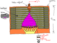
Here's my general idea for the plasma chamber. The attachment shows the upper section, which is pretty much Hill's design, except that I'm using MHCD instead of pipe cathodes delivering He. The variable resistors attached to the MHCDs are for equalization and will be the minimum value needed to give enough range, to minimize dissipation. Five Watt cermets probably should do. Equidistance from the adjustable anode should do most of the equalization anyway. The chamber I think will be easiest to make by baking pottery clay. The heatsink I can just make of parallel sheets of metal, and the front window from either also clay, or piece of glass as in Hill's setup. The hardest thing are the MHCD electrodes. The conductor material has to withstand high temperature and oxidation. Maybe tungsten or some appropriate alloy, both of which will be hard to find. I used copper to experiment, and it doesn't last. The dielectric in-between can be mica, but alumina will be better, but once again hard to find. Drilling small holes is extremely difficult as I don't have the right tool. Diffraction is dealt with by acoustic padding. Mineral wool will probably withstand the temperature.
Attachments
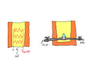
The lower section preheating the incoming air to create the steep thermal gradient plasma envelope is shown in this attachment, in two possible versions. The flow needed is pretty low, so in the first one with ohmic heating, just convection may be sufficient. If there is too much ozone (though I think the plasma temperature will create much less than, say, corona discharge type tweeters), the second version may be necessary. Very little gas would be used, as the flame only needs to be of minimal size. The mix can be adjusted to minimize leftover oxygen (no danger of too much gas as any extra will finish combustion in the chamber, though it will dirty the electrodes). Leftover ozone can be dealt with by a catalyst coated screen over the window. UV remains an issue I can't figure out how to solve, but I guess as it wasn't dealt with at all in Hill's design, it's not too much of a problem.
Tuning the frequency response is done by adjusting anode distance, incoming flow and temperature, heatsink cooling, and padding. The latter makes a lot of difference, as can be seen in the graphs on Jay Philippbar's page which I linked to previously in this thread.
I'm wondering if instead of a linear array of MHCDs, a similar plasma shape can be achieved with a long slot. The MHCD effect depends on oscillation of electrons in the hollow, so I'm not sure how it would work in a different shape.
Many possibilities for failure in this project, but I find it very interesting so I think I'll keep at it for now. Due to how busy I am, it could take a year until I finish it...
Attachments
According to "Electrical and Optical Characteristics of RF Driven Hollow Slot Microplasma Operating in Open Air" A. Yalin, Z. Yu, S. Ovidiu, K. Hoshimiya and G. J. Collins Appl. Physics Letters Vol 83 pp 171-175, slots can be used instead of circular microhollows. That geometry might be easier for me to construct, rather than trying to drill tiny holes.
Continued from email discussion
Usually the output is in parallel with the amplifier-output-device-to-ground, so there are two paths for the output stage current -- one through the amplifier and one through the driver. But here the output (discharge) is in SERIES with the output device, and the current through it is the same as the current through the discharge. The output power is current times voltage across the discharge. The plasma power would only be proportional to the signal if voltage across the discharge is either constant or varies proportionally to the current. If the tube only drops a small part of the voltage, most of the power can be dissipated in the discharge; the 20% doesn't apply in this situation. Yes, the actual sound produced is only a fraction of plasma power, but that has to do with the plasma's efficiency as a driver, not the amplifier efficiency.
What do you mean, 1/200th of the input? You mean the voltage variation? How's that 1/200th of the input?
Well, I'm pretty new to this. Over-reliance on the simulator, etc. That's why I'm asking all these questions.
Say there's a large swing on the input. The current sink pulls a large current. For the sound production to be linear, the discharge's change of power has to be proportional. However, the voltage at the top of the plasma will vary, say as much as 10% as you said before. Due to the reactance of the PSU, it will not be in phase with the current the sink is pulling, and so the power dissipated in the plasma (and therefore sound wave) will not be directly proportional to the signal -- distortion. I can't see what I'm figuring wrong here.
The way class A works is, at zero signal, all the consumed power is dissipated in the amplifier. Obviously, there is no output power. At maximum signal, DC current and voltage are still about the same, but there is maybe 20% output power now. So clearly, the dissipation goes down as signal output rises.
Usually the output is in parallel with the amplifier-output-device-to-ground, so there are two paths for the output stage current -- one through the amplifier and one through the driver. But here the output (discharge) is in SERIES with the output device, and the current through it is the same as the current through the discharge. The output power is current times voltage across the discharge. The plasma power would only be proportional to the signal if voltage across the discharge is either constant or varies proportionally to the current. If the tube only drops a small part of the voltage, most of the power can be dissipated in the discharge; the 20% doesn't apply in this situation. Yes, the actual sound produced is only a fraction of plasma power, but that has to do with the plasma's efficiency as a driver, not the amplifier efficiency.
Yes, but the voltage is 1/200th of the input.
What do you mean, 1/200th of the input? You mean the voltage variation? How's that 1/200th of the input?
Haven't you ran any good old pencil and paper calculations on reactance and such?
Well, I'm pretty new to this. Over-reliance on the simulator, etc. That's why I'm asking all these questions.
Say there's a large swing on the input. The current sink pulls a large current. For the sound production to be linear, the discharge's change of power has to be proportional. However, the voltage at the top of the plasma will vary, say as much as 10% as you said before. Due to the reactance of the PSU, it will not be in phase with the current the sink is pulling, and so the power dissipated in the plasma (and therefore sound wave) will not be directly proportional to the signal -- distortion. I can't see what I'm figuring wrong here.
Prune said:Usually the output is in parallel with the amplifier-output-device-to-ground, so there are two paths for the output stage current -- one through the amplifier and one through the driver. But here the output (discharge) is in SERIES with the output device, and the current through it is the same as the current through the discharge.
Huh? The output is in SERIES with the amplifier. Push pull is in series in two directions. That's kinda complicated to see in class A but it's true. It is true in AC terms in a parafeed circuit.
The output power is current times voltage across the discharge. The plasma power would only be proportional to the signal if voltage across the discharge is either constant or varies proportionally to the current. If the tube only drops a small part of the voltage, most of the power can be dissipated in the discharge; the 20% doesn't apply in this situation.
Indeed, it will be far lower, since you'll get a far less symmetrical voltage swing (assuming the discharge is approximately resistive).
What do you mean, 1/200th of the input? You mean the voltage variation? How's that 1/200th of the input?
The power supply chain is a low-pass attenuator and nothing else. Say you introduce a 1kHz signal at the far end (representing the amplifier and its current draw variation). If you have a certain voltage or current through this signal source, it will be attenuated when it encounters the filter, and likewise shifted in phase. But this phase has absolutely NO concern, because 1. it is so extremely small; 2. the shift is only 90 degrees maximum, and 3. you don't even have another stage feeding off of this which could cause a phase shift oscillator type behavior (i.e., power supply related motorboating).
Well, I'm pretty new to this. Over-reliance on the simulator, etc. That's why I'm asking all these questions.
Well then honestly, sit down with some books and a pad of paper. See capacitors and inductors as resistors dependent on frequency, and their reactances as phase-shift elements. Run impedance calculations, noting for instance that power supply rails appear shorted together and thus Zo of a stage = Rp || RL || Rg (plate and grid leak resistors in the circuit). They key to doing ANYTHING well is to understand it. I don't like simulators because they encourage an almost useless tweaking process, which can often result in wrong, misinterpreted, or overly complicated results.
I can't see what I'm figuring wrong here. [/B]
That the same current applied (in series, because all these elements carry that same load and signal current) develops almost nil voltage across the capacitor's reactance. Say you have 50uF and apply a 100Hz 200mA RMS AC signal to it: the reactance is 32 ohms and thus develops 6.4V, as you noted out of phase; this is 0.3% of the total power supply voltage. Negligible.
As for "power linearity", constant current vs. constant voltage, and all that hubub, it is ALL speculation. Please get around to actually building the final model of discharge device you will be using and take some AC and DC measurements of V vs. I. Then, if possible, record the output signal and note what function of distortion it creates and if it follows voltage, current or power. Then, and only then, can we decide what kind of actions must be taken to correct it.
Tim
The definition of efficiency I'm using here is the fraction of total power (including the large DC component) coming from the PSU that is dissipated in the discharge (as opposed to the resistances in the PSU, and the amplifier's output device). If I get 2 kV across the discharge, and 350 mA current, on average, the average plasma power is 700 W. A couple hundred watts dissipated in the power supply, and a couple hundred (I hope not much more) in the ceramic tetrodes, that makes for over 50% efficiency. (Sure, sound is only a fraction of plasma power, the rest is heat, light and UV, but that's plasma efficiency, not amplifier efficiency.)Indeed, it will be far lower, since you'll get a far less symmetrical voltage swing (assuming the discharge is approximately resistive).
I got confused by the 10% you said in the previous email, I thought you meant that's what the variation would be.1. it is so extremely small
I know in tube circuits that would be considered low distortion, but I was hoping to do a little bit better. And since the voltage varies only a bit, a solid state pass device with protection would work, no? That's why I asked about Broskie's regulator design.6.4V, as you noted out of phase; this is 0.3% of the total power supply voltage. Negligible.
Well, I already know it's neither, and that's no speculation -- there's already been plenty of research done into these types of discharges by others.constant current vs. constant voltage, and all that hubub, it is ALL speculation.
This is a problem -- I don't really have the right tools to make a proper AC measurement.Please get around to actually building the final model of discharge device you will be using and take some AC and DC measurements of V vs. I.
Last time I checked distortion analyzers were extremely expensive...Then, if possible, record the output signal and note what function of distortion it creates and if it follows voltage, current or power.
Prune said:(Sure, sound is only a fraction of plasma power, the rest is heat, light and UV, but that's plasma efficiency, not amplifier efficiency.)
Yes, and you will intrinsically get more sound output if you run a wider dynamic band of voltage and/or current, i.e. power variation.
I got confused by the 10% you said in the previous email, I thought you meant that's what the variation would be.
Oh, that was DC based on your impedance figure. Typical regulation (DC, passive) specs are accepted as 5 or 10%, transformers for instance. As regards DC stability, your supply is fine.
I know in tube circuits that would be considered low distortion, but I was hoping to do a little bit better.
Boris, no one can hear 0.3% and no one cares. SS looks like it cares about 0.000028% THD, but that's just masturbatory posturing.
Well, I already know it's neither, and that's no speculation -- there's already been plenty of research done into these types of discharges by others.
Alright, may I please see an actual V vs. I chart with values present?
This is a problem -- I don't really have the right tools to make a proper AC measurement.
Sure 'ya do. Current sense resistor to ground, modulate current and voltage with an output transformer in series (as the original design was wired). Just needs a two-channel scope, a few parts and a stocky enough signal source (power amp).
Last time I checked distortion analyzers were extremely expensive...
Pffbt.. you could even record the response right on your computer, then you'd have a readout and recording of the waveform right there! You can try something like Audacity, which is freeware.
If nothing else, you can visually compare the transmitted waveform to the input waveform and figure what kind of equation or response produces it. Then figure a way to reduce or cancel it (current or voltage feedback, for instance).
Tim
Well, if my supply voltage is 2.5 kV, then the maximum voltage I can swing is 2.5 kv (actually it depends on crossover frequency, as if it's too low, then a downwards swing even not all the way down could extinguish the discharge).Yes, and you will intrinsically get more sound output if you run a wider dynamic band of voltage and/or current, i.e. power variation.
Hehe, you ought to say that in the SS forums.Boris, no one can hear 0.3% and no one cares. SS looks like it cares about 0.000028% THD, but that's just masturbatory posturing.
BTW, I prefer Bobby -- Boris sounds too Russian.Um, I actually posted a bunch of references already. DC characteristics: normal discharge (no MHCD) is constant voltage; with MHCD sustaining it, it's either like an abnormal or subnormal discharge (resistive or negatively resistive). AC characteristics -- no idea, because I couldn't find any info on the reactances of such discharges. There are papers dealing with RF powered discharges, but...my technical understanding is insufficient to make any predictions here. So I can't do anything about that until I buy an oscilloscope.Alright, may I please see an actual V vs. I chart with values present?
There was no design, that was merely my initial experimentation with lower voltage. I don't have a transformer that will withstand 2.5 kV swing. I have a couple of 1.5 kV SS devices. Any suggestion for a simple circuit with these two stacked I can use for testing? I was initially planning to use them for regulation.modulate current and voltage with an output transformer in series (as the original design was wired).
I've read that while computer cards with mikes are good enough for SPL measurements, they are not accurate enough for distortion analyzing. Plus, my sound card is four years old...you could even record the response right on your computer
I ask again, why not just feedback a signal proportional to the actual power in the discharge?Then figure a way to reduce or cancel it (current or voltage feedback, for instance).
Prune said:
Well, if my supply voltage is 2.5 kV, then the maximum voltage I can swing is 2.5 kv (actually it depends on crossover frequency, as if it's too low, then a downwards swing even not all the way down could extinguish the discharge).
For a pure resistive load, the maximum output will be at 1/2 B+ bias for +/-1.25kV peak swing in your situation. The problem here is nonlinear behavior in the discharge, but in general, keeping a large bias in something will not allow greater power. You don't bias a 6L6 at -2V grid...
Um, I actually posted a bunch of references already.
But only speculatory ones. The behavior varies IMMENSELY with current density. You don't even *know* which region yours will fit into, so we can only make vague guesses at its response, let alone behavior as a load.
There was no design, that was merely my initial experimentation with lower voltage. I don't have a transformer that will withstand 2.5 kV swing. I have a couple of 1.5 kV SS devices. Any suggestion for a simple circuit with these two stacked I can use for testing? I was initially planning to use them for regulation.
Oh, right.
Simple enough, put the transformer on the ground side.
I've read that while computer cards with mikes are good enough for SPL measurements, they are not accurate enough for distortion analyzing. Plus, my sound card is four years old...
Errr... they've had 16 bit precision audio for over a decade. That's what, -80dB distortion floor?
I'd be far more worried about the mic's response.
Tim
Also, the transformer (a regular power transformer, I don't have any output transformers) is not very good at 500 Hz, my intended minimum crossover frequency.
As for the microphone response, http://sound.westhost.com/project93.htm shows that the cheap electrets have very flat frequency response. I'm more worried about the distortion and (lots of) noise my old SBLive card has on it's analog inputs. Once I tried to measure my DAC performance with RMAA, but any results were lost in the high noise floor of the crappy Creative product. It's true I suppose, these cards are only good for gaming and nothing else.
As for the microphone response, http://sound.westhost.com/project93.htm shows that the cheap electrets have very flat frequency response. I'm more worried about the distortion and (lots of) noise my old SBLive card has on it's analog inputs. Once I tried to measure my DAC performance with RMAA, but any results were lost in the high noise floor of the crappy Creative product. It's true I suppose, these cards are only good for gaming and nothing else.
- Status
- This old topic is closed. If you want to reopen this topic, contact a moderator using the "Report Post" button.
- Home
- Amplifiers
- Tubes / Valves
- Plasma/ionic