Hi folks, I want to try with & without opt, only one tube per stereo, attached a couple of schematics & valve data sheet, I will try with & without feeedback, with opt & without opt capacitor. The opt is Edcor USA GXSE5-600-15K 5W 15K-600Ohms. I want advice what of the two schematics sounds better, also I need advice about the new B+ using the 15k-600 ohms opt target of Va is 90V.
TIA
Felipe
TIA
Felipe
Attachments
I doubt if the 3.6V cell can long survive in the cathode connection, so I would immediately rule that out. Amplifier performance characteristics will change with volume setting because input impedance changes and input Z is part of the feedback network. The B+ voltage calculation requires knowledge of OPT primary DC resistance. Can we assume that your bias current target is 15mA? Why so low?
A 15K load line with operating point of 15mA and 220V looks good for this job. If you use an autoformer input volume control, then the feedback circuit ought to work nicely because the AVC presents a low impedance to the feedback network at all settings.
I'm guessing that you want something near unity gain overall. Without doing the math, I suppose an input resistor of 100K and a feedback resistor of 680K would come pretty close. The cathode bias cap must be bypassed to achieve significant feedback, and even then FB will be only 8~9dB.
I'm guessing that you want something near unity gain overall. Without doing the math, I suppose an input resistor of 100K and a feedback resistor of 680K would come pretty close. The cathode bias cap must be bypassed to achieve significant feedback, and even then FB will be only 8~9dB.
In other thread EURO21 member published the attached schematic but the sound level is very low (measured with scope 10dBs aprox.) , only draws 11.65 mA per channel and sometimes with a big buzz like a truck horn with high volume level, can be the 1K grid resistor a very high value?
Fixed.
Fixed.
Attachments
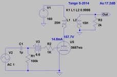
What kind of transmformer is a Tango S-2014? I can't find any spec sheets for it.
The problem I see with using a 5687 for a 'spud' headphone amp is that it has gain of only about 10 to 15X.
The plate (anode) resistance of a 5687 with plate current of 20mA is going to be in the vicinity of 2k ohms.
A proper output transformer for a pair of headphones will need to have a primary impedance of about 5k ohms with a secondary of about 50 ohms to 250 ohms. Let's say you have typical 32 to 50 ohm impedance headphones like those from Grado, Audio Technica or Fostex. That's a 5k:50 ohm transformer needed, which will have a turns ratio of 10:1.
(Keep in mind that a 5687 with only 12mA of plate current will have rp of more like 3k ohms. That's too high to use with a 5k primary. To get the rp down to 2k ohms, you need to draw at least 15mA plate current.)
That means with 1V RMS signal input, and the 5687 amplifying that by 10X (to 10V RMS), the transformer will step that back down to 1V RMS. That means unity gain. Since output transformers will have insertion loss of maybe 2dB, the end result will likely be quite a bit less than unity gain.
Will that be enough gain? Can you accept an amplifier that actually makes the audio signal from your iPhone quieter?
Most headphone amps I've seen have a final gain of between 2X and 8X. In order to achieve that much gain with that 5k:50 ohm OPT (10:1 turns ratio), you'd want a triode with more like 40X gain. That's why those high-gm RF pentodes wired in triode are popular for this type of 'spud' amp. In order to get rp = 2k ohms with 40X gain (mu), you need a tube with gm = 20mA/V. That's high gm for a vacuum tube, and that's why you see tubes like D3a, 7788, 6J52P, 6J9P, E180F, 5842, etc. used for this kind of thing.
--
You will want a 47u coupling cap if you want any bass...
Or you could use an ACF power buffer to drive them if you have enough gain beforehand.
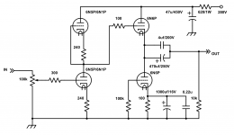
Or include the gain stage as follows:
It takes an extra tube, but I'd build this instead. Based on Broskies Aikido. Just sub the 5687 for the 6N6P and play ball. As drawn, it will drive 32 Ohm headphones. If you don't need that just make the coupling cap 47u instead of 470u.
Or you could use an ACF power buffer to drive them if you have enough gain beforehand.
Or include the gain stage as follows:
It takes an extra tube, but I'd build this instead. Based on Broskies Aikido. Just sub the 5687 for the 6N6P and play ball. As drawn, it will drive 32 Ohm headphones. If you don't need that just make the coupling cap 47u instead of 470u.
Attachments
Last edited:
@rongon
@kodabmx
Thanks for advices, at the moment the real OPT is an EDCOR GXSE5-15k_600 ohms for a load of 300 ohms (Sennheiser HD600), I have in mind to change the bias point to 100V at plate and 3.3V at grid drawing 15mA to try if SQ is improved. What do you think is the best bias point? What are the specs requirements for both bias 100V & 150V?
Tango OPT is a simulation of EURO21 diya member.
TIA
Felipe
Last edited:
The OPT is a part of the circuit. If you put any random OPT into your simulation, you're changing the circuit. You'll get results that don't predict what you're getting in real life.
A 15k:600 transformer used with 300 ohm load will look like 7.5k:300, which should be fine for a 5687. That's a 5:1 turns ratio, so the resulting gain should be usable too.
The only problem is the primary inductance, which tends to be kind of low on those Edcor transformers. The primary inductance is not stated on the Edcor site, but I guess it would be around 5 to 8 henries. Have you measured it?
If it's only 8H (which is quite possible), then biasing your 5687 'cold', which increases rp, will raise the -3dB rolloff frequency on the low end (the high pass filter's "fc"). That will roll off the bass.
If the 5687 is biased to 11mA Ip, then its rp will probably be around 3500 ohms (just a guess, I haven't looked at the datasheet). If the primary inductance of the OPT is only 8H, the 3.5k-8H high pass filter will have fc of 70Hz. In other words, practically no bass response, unless you goose it up somehow.
Increasing the 5687 Ip to 20mA, rp should get down to about 1800 ohms. Into that same 8H primary, the fc should be around 36Hz. Still high, but now you should hear at least some bass from the resulting amplifier.
Hopefully the primary inductance of your OPT is more like 15H, rather than only 8H. But I don't know what it is. Can you measure it?
--
Last edited:
It's not my simulation, it's a kind simulation of euro21 diyaudio member, I guess the opt used for simulation it's similar to mine but I'm not sure. I measure the primary inductance and let you know asap.
10H
I guess the problem of these OPT is Frequency Response 40~18K Hz., <1dBu
Attached Tungsol 5687 datasheet
10H
I guess the problem of these OPT is Frequency Response 40~18K Hz., <1dBu
Attached Tungsol 5687 datasheet
Attachments
OK.
Let's look at the 5687 datasheet.
http://www.mif.pg.gda.pl/homepages/frank/sheets/127/5/5687.pdf
Look at the very last graph in that datasheet. It shows plate resistance (rp), amplification factor (mu), and transconductance (gm) for various operating conditions.
If Vp = 180V and Ip = 11mA, then rp = 3.5k ohms.
If Vp = 180V and Ip = 20mA, then rp = 2.1k ohms.
Calculating f3 using rp as the series resistance and the OPT primary as the shunt inductance, we plug those values into this handy calculator:
(Sample)LR Low-pass Filter Design Tool - Result -
If the 5687 Ip = 11mA, then fc = 56Hz
If the 5687 Ip = 20mA, then fc = 34Hz
The rp doesn't get much lower at higher plate currents. It will be really hard to get rp lower than 2k without frying the 5687.
In other words, using a 5687 in this circuit will give you an amp that's -3dB at about 35Hz.
(That's -1dB at about 60Hz, not 40Hz, when used with a 5687 at Ip = 20mA. Specs are just guidelines, not etched in stone.)
--
Last edited:
- Status
- This old topic is closed. If you want to reopen this topic, contact a moderator using the "Report Post" button.
- Home
- Amplifiers
- Headphone Systems
- 5687 headphone amp