I'm beginning a build of the VTA / Tubes4HiFi PH16 phono preamp. I've built a Tubelab SE 300B but am still pretty green, so I'd like to use this thread to ask questions and document the process for other builders of this kit.
This will be a stock build, using the toroidal power transformer that Roy Mottram offers as an option with the kit. I will be using an MC cartridge with Sowter 9570z step-up transformers wired directly between the input RCA jacks and the PCB.
Right now I'm trying to figure out the chassis layout given the tight constraints in my equipment cabinet, and have come up with two possibilities so far.
(1) Build it in two 10" x 6" aluminum enclosures -- one for the PS and one for the RIAA section -- connected by an umbilical cable for maximum noise reduction and magnetic shielding of the inputs/SUTs.
(2) Put everything into a single 12" x 10" or 12" x 12" chassis (can't go bigger than that)
First question: Is a two-enclosure build overkill?
Secondly, do you think a single 12" x 10" or 12" x 12" chassis would provide enough distance between the transformer and the phono inputs/SUTs?
Thanks,
Jeff
Last edited:
In addition to two 10" x 6" x 2" Hammond aluminum chassis (and associated hardware), I've ordered shielded continuous flex cable (300 VAC, 6 amp) from Grainger for the umbilical. If you do a two-chassis build, you need 7 conductors -- two for B+1, two for B+2, two for F +/-, one for GND. My umbilical will probably end up being 18" - 24" long, so ordered 3' of this 7 conductor, 20awg cable.
I also ordered a Conxall connector and socket from Allied for the power supply chassis. The other end of the cable will be hard wired to the RIAA section and held secure with a cable clamp and small L bracket.
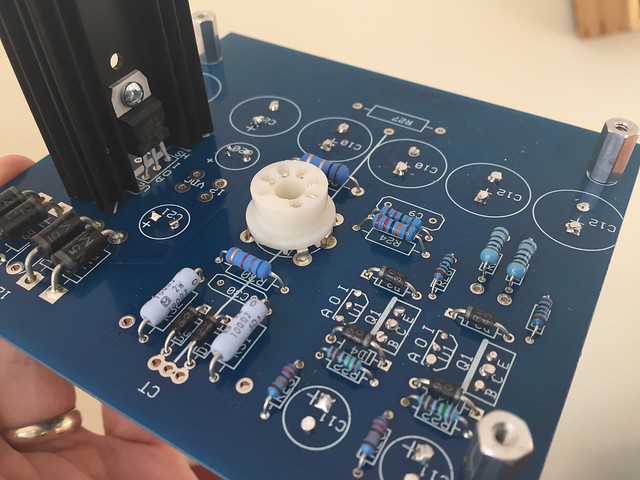
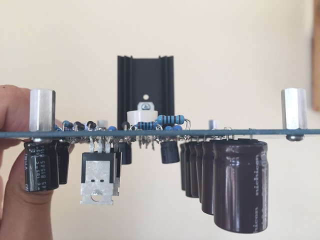
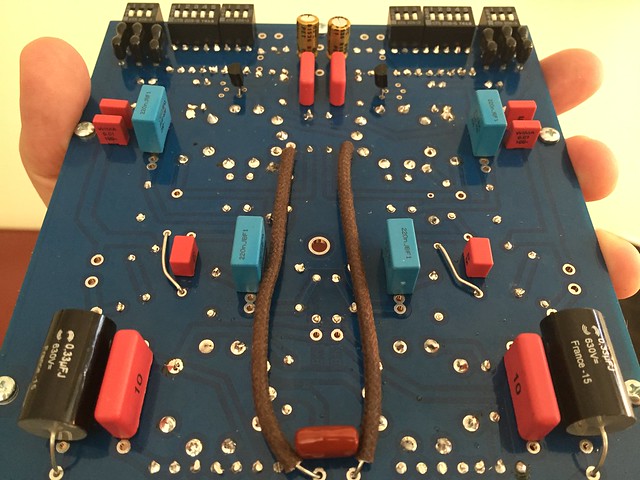
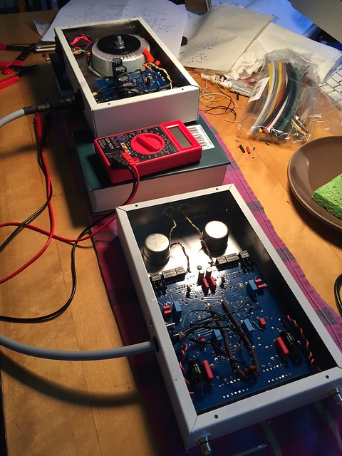
Today I populated the board for the power supply. For the most part, I'm doing hot stuff up top and capacitors on the bottom, although I did put the TIP50s and SILR regulators on the bottom for space reasons, since the boards will hang from the chassis tops to allow the tubes to show. I'm getting a kitchen sink basket strainer to cover/vent the JFET heatsink.
 IMG_5913 by jeffdrouin, on Flickr
 IMG_5910 by jeffdrouin, on Flickr
I also ordered a Conxall connector and socket from Allied for the power supply chassis. The other end of the cable will be hard wired to the RIAA section and held secure with a cable clamp and small L bracket.
Today I populated the board for the power supply. For the most part, I'm doing hot stuff up top and capacitors on the bottom, although I did put the TIP50s and SILR regulators on the bottom for space reasons, since the boards will hang from the chassis tops to allow the tubes to show. I'm getting a kitchen sink basket strainer to cover/vent the JFET heatsink.
IMG_5913 by jeffdrouin, on Flickr
IMG_5910 by jeffdrouin, on FlickrThe stand offs and the way you have mounted the caps doesnt make sense? Whats wrong with mounting everything on 1 side?
There is no signicant heat coming off anything on that board in comparison to many other very successful tube preamps that had way more tubes on one side and produced alot more heat.
You have made mounting more difficult and the whole area is thicker and less compact.
Holding the caps off board is also a mistake. Take advantage of the soft rubber supports of the electrolytics pressed against the pcd for vibration control.
If you do a seperate PS box consider zero connectors and hard soldering all cable leads (Audible Illusions 3 series)
The famous Audio Research sp10/11 seperate PS and connectors had many issues with their connectors.
I would rethink it and not be to overly concerned with heat issues here
Regards
David
Last edited:
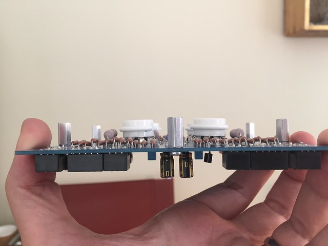
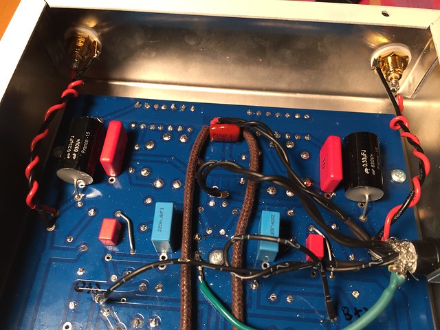
I want to display the tubes, so the PCB will mount under the top of the chassis. Since the distance between PCB and chassis top is about 1/2", that means there isn't enough space there for longer components like the capacitors, so they go underneath. I did the same thing in my 300B power amp and it works fine.
I thought about hard wiring both ends of the cable but wanted flexibility in moving the pieces. Also, they're going into a cabinet with a backing and will be on separate shelves, so they need to come apart somehow. Can always change it if there's a problem.
I thought about hard wiring both ends of the cable but wanted flexibility in moving the pieces. Also, they're going into a cabinet with a backing and will be on separate shelves, so they need to come apart somehow. Can always change it if there's a problem.
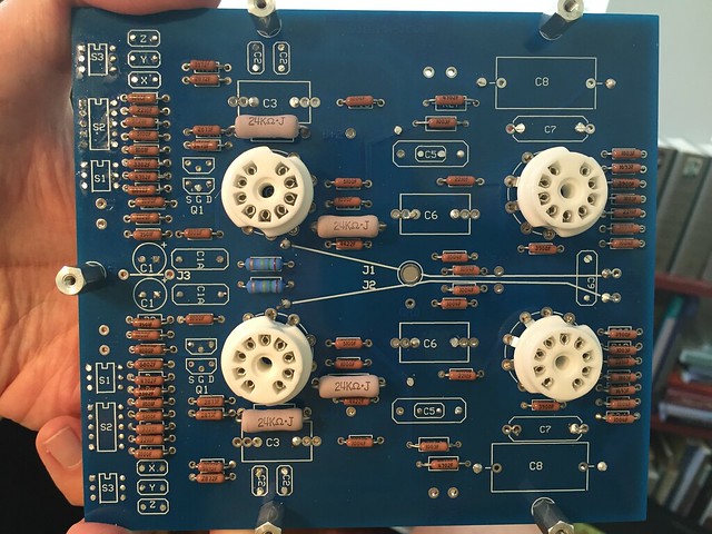
Today I finished the RIAA section. I've been planning the chassis layouts and hope to start drilling this weekend.
 IMG_6040 by jeffdrouin, on Flickr
 IMG_6041 by jeffdrouin, on Flickr
 IMG_6043 by jeffdrouin, on Flickr
IMG_6040 by jeffdrouin, on Flickr
IMG_6041 by jeffdrouin, on Flickr
IMG_6043 by jeffdrouin, on FlickrThe chassis are drilled and painted, so the PH16 is ready for final assembly.
What do we think would be a good wire to use from the PCB to the output RCA jacks?
Lying around in my workshop is some 20 AWG solid copper insulated/braided wire from AES, or I could get 22 AWG solid copper hookup wire from Radio Shack. Any alternative suggestions?
Not sure what a good material & gauge would be for the low power levels of the phono pre.
I think I'll go with 22 AWG.
Do you have any specific recommendations on how to ground two chassis connected by an umbilical?
This is a little more complex than the power amp I built, in which the (single) chassis, metal parts, and signal grounds ultimately connected to earth ground through a star point. I thought I'd apply the same principle to this two-chassis build.
Does this seem right?
* Star ground point on the PS chassis connects to ground lug on IEC power inlet and GND pad on PS PCB, referencing everything to earth ground potential
* GND pad in RIAA PCB connects to GND pad in PS PCB through the umbilical
** Since the input and output jacks connect to GND on the RIAA PCB, their signals are therefore grounded through the umbilical connection to the PS (which then connects to earth ground in the star point)
* For RIAA chassis safety, the GND pad in RIAA PCB connects to RIAA chassis, which grounds that chassis through the umbilical connection to PS
* The umbilical cable contains 7 20awg conductors and has a braided shield. So either both ends or one end of the shield should connect to the ground conductor to aid the flow to earth ground and capture any stray EM activity and send it out through the wall. (not sure if this would create a ground loop)
Sorry if that's obtuse. Basically, I'm trying to describe a situation in which all the signal and metal parts in both chassis flow to earth ground through a star ground point in the PS chassis.
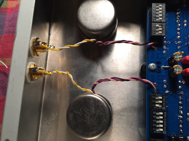
Roy confirmed that the proposed grounding scheme should work. I see that some people connect the ground tabs of the input RCA jacks together if they're using SUTs (like I am) between jacks and PCB. I'll try it without first to hear if it hums.
Today I spent some time wiring the PS chassis. I cleaned the PS and phono PCBs with 91% isopropyl alcohol. Then I marked the test and phono section connection points on the underside of the PCB, which is visible when the chassis bottom plate is removed. The PT and IEC inlet/switch/fuse are all wired up and the HV and filament leads are connected to the PCB.
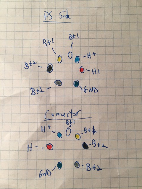
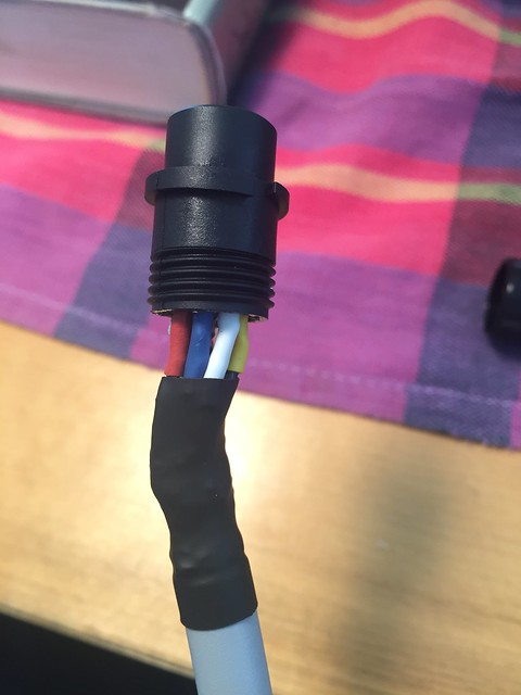
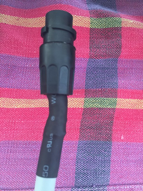
Now it's time to wire the connections from the PS to the phono section. There is a 7-conductor umbilical cable with circular connectors on the PS side, which will be hard wired to the phono side. So I figured out which pinout works best for the circular socket and connector given the points on the PCB from which the twisted pairs will come, color-coded with 7 different colors of heatshrink.
 umbilical by jeffdrouin, on Flickr
I was hoping to get more done today but this took quite a while.
Today I spent some time wiring the PS chassis. I cleaned the PS and phono PCBs with 91% isopropyl alcohol. Then I marked the test and phono section connection points on the underside of the PCB, which is visible when the chassis bottom plate is removed. The PT and IEC inlet/switch/fuse are all wired up and the HV and filament leads are connected to the PCB.
Now it's time to wire the connections from the PS to the phono section. There is a 7-conductor umbilical cable with circular connectors on the PS side, which will be hard wired to the phono side. So I figured out which pinout works best for the circular socket and connector given the points on the PCB from which the twisted pairs will come, color-coded with 7 different colors of heatshrink.
umbilical by jeffdrouin, on FlickrI was hoping to get more done today but this took quite a while.
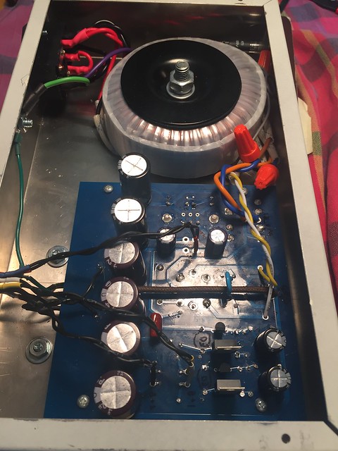
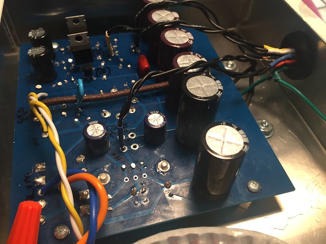
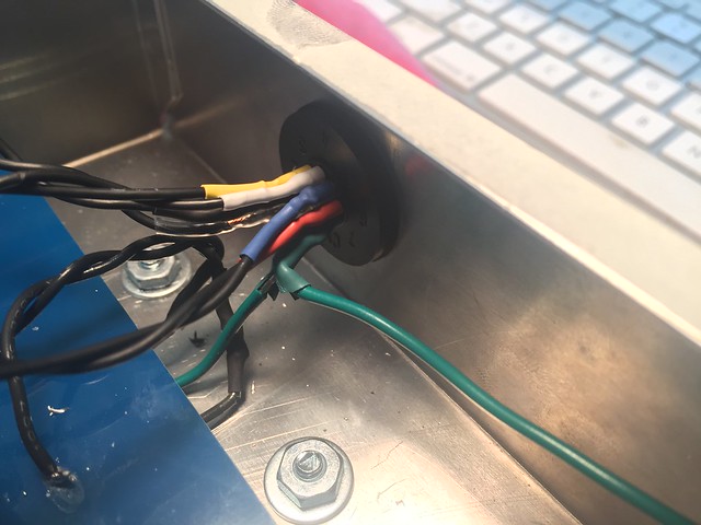
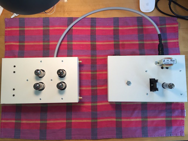
Power supply chassis is finished and wired up. Here you can see B+, filament, and ground wires from the PS board hooked up to the circular socket inside the chassis and also in the connector on the umbilical cord. A star ground point references chassis, power, and signal grounds to earth potential. The other side of the cord will be hard wired to the phono board. Not my neatest work but everything is connected correctly.
Also I took AVWERK's advice and moved the caps right up to the PCB to allow the bottoms to dampen vibration.
I should be able to finish wiring up the phono chassis tomorrow or Friday, and then do the checkout procedure.
It would have been *so much* easier to do this in one chassis, so I hope it works!
 Untitled by jeffdrouin, on Flickr
 Untitled by jeffdrouin, on Flickr
 Untitled by jeffdrouin, on Flickr
 Untitled by jeffdrouin, on Flickr
 Untitled by jeffdrouin, on Flickr
Also I took AVWERK's advice and moved the caps right up to the PCB to allow the bottoms to dampen vibration.
I should be able to finish wiring up the phono chassis tomorrow or Friday, and then do the checkout procedure.
It would have been *so much* easier to do this in one chassis, so I hope it works!
Untitled by jeffdrouin, on Flickr
Untitled by jeffdrouin, on Flickr
Untitled by jeffdrouin, on Flickr
Untitled by jeffdrouin, on Flickr
Untitled by jeffdrouin, on Flickr
Last edited:
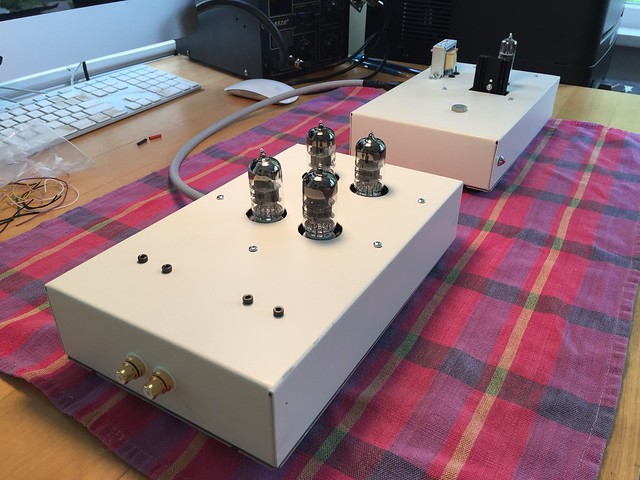
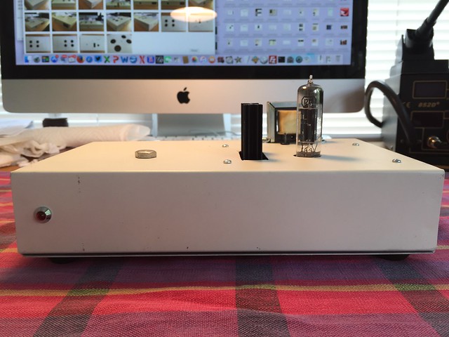
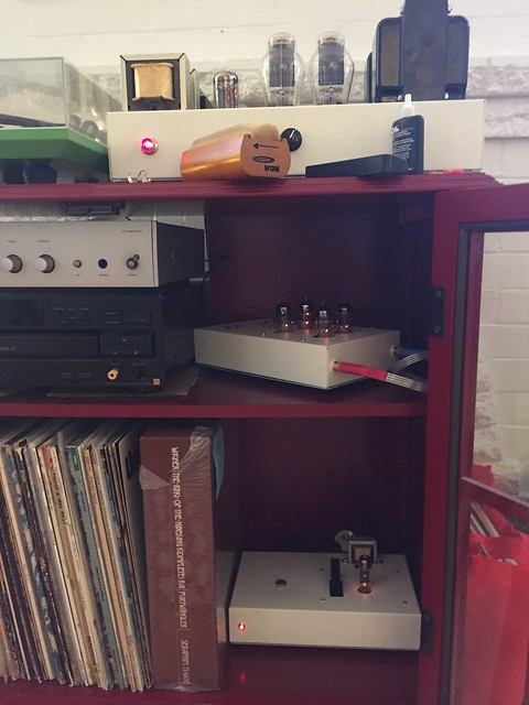
The build is finished and tested. After a couple of adjustments (changing to the 220V winding instead of 240, resoldering an insecure resistor that was causing low filament voltage), the PH16 is up and running.
I spent two hours listening to Merle Haggard, Loretta Lynn, Tom Jones, The Turtles, and The Young Rascals. Even though the PH16 needs time to break in, it sounds excellent. Very detailed, gorgeous tone (esp. percussion), plenty of air, quick transients, and very involving.
I'm having FEELINGS right now.
A more in-depth review is forthcoming once it's broken in, but color this builder happy.
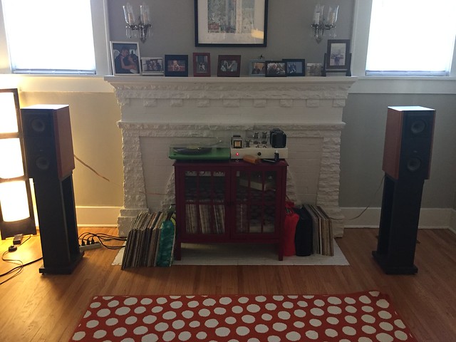
Signal chain is as follows:
Denon DL-301ii
Sowter 9570z step-up transformers (wired right into the PH16 inputs)
PH16
Tubelab SE 300B (has volume control)
JM Lab Electra 905
The PH16 provides more than enough gain to drive the TSE and the Electras to concert volume; this is by far the loudest this system has ever played.
I was thinking my next project would be a line stage, though I definitely don't need more gain from the PH16. It would be nice to have source selection and a little more gain from the CD player, though.
I eventually want to try a transistor-free SET for a more sweet vintage sound, like a pair of Fi Primer 300B monoblocks (6SN7 capacitor-coupled to 300B), which would definitely need a line stage.
So I might try a 26 or 10Y line stage from schematic.
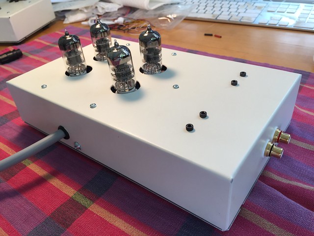
Anyway, here's what my PH16 looks like:
 VTA PH16 by jeffdrouin, on Flickr
 VTA PH16 by jeffdrouin, on Flickr
 VTA PH16 by jeffdrouin, on Flickr
 VTA PH16 by jeffdrouin, on Flickr
 VTA PH16 by jeffdrouin, on Flickr
 VTA PH16 by jeffdrouin, on Flickr
 VTA PH16 by jeffdrouin, on Flickr
 VTA PH16 by jeffdrouin, on Flickr
 VTA PH16 by jeffdrouin, on Flickr
I spent two hours listening to Merle Haggard, Loretta Lynn, Tom Jones, The Turtles, and The Young Rascals. Even though the PH16 needs time to break in, it sounds excellent. Very detailed, gorgeous tone (esp. percussion), plenty of air, quick transients, and very involving.
I'm having FEELINGS right now.
A more in-depth review is forthcoming once it's broken in, but color this builder happy.
Signal chain is as follows:
Denon DL-301ii
Sowter 9570z step-up transformers (wired right into the PH16 inputs)
PH16
Tubelab SE 300B (has volume control)
JM Lab Electra 905
The PH16 provides more than enough gain to drive the TSE and the Electras to concert volume; this is by far the loudest this system has ever played.
I was thinking my next project would be a line stage, though I definitely don't need more gain from the PH16. It would be nice to have source selection and a little more gain from the CD player, though.
I eventually want to try a transistor-free SET for a more sweet vintage sound, like a pair of Fi Primer 300B monoblocks (6SN7 capacitor-coupled to 300B), which would definitely need a line stage.
So I might try a 26 or 10Y line stage from schematic.
Anyway, here's what my PH16 looks like:
VTA PH16 by jeffdrouin, on Flickr
VTA PH16 by jeffdrouin, on Flickr
VTA PH16 by jeffdrouin, on Flickr
VTA PH16 by jeffdrouin, on Flickr
VTA PH16 by jeffdrouin, on Flickr
VTA PH16 by jeffdrouin, on Flickr
VTA PH16 by jeffdrouin, on Flickr
VTA PH16 by jeffdrouin, on Flickr
VTA PH16 by jeffdrouin, on Flickr- Status
- This old topic is closed. If you want to reopen this topic, contact a moderator using the "Report Post" button.
- Home
- Amplifiers
- Tubes / Valves
- VTA PH16 Build