. .. or Mediocre, aka Medi-End ))
Hi everybody, finally, after gathering myself and some parts I go up for a one.
The Dual-SE topology has been around for awhile:
Bel Canto SET 80 monoblock power amplifier | Stereophile.com
I got the idea to build it on 6AD10 compactrons and initially purchased a pair of ?USA? new-mades, those are with side getter and nice glow of filaments can be seen through the top. The supplier said they are made by Sylvania, had many of them in stock two months ago, but suddenly all batch got sold out before I inquired for another pair.
So I collected several old AD10s by GE, but I must tell it is hit-and-miss - I got two pairs out of 8, with two seem about worn out. Another option would be 6T10 (12T10) which is easier to get NOS:
5 Pcs National 12T10 Audio Radio Vacuum Tubes | eBay
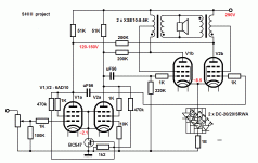
Here is the schematics, very simple:

I have had it on breadboard for 3 days by now, and the first impression is not that awesome. The major advantage of DSE is the micro dynamics, m-m-m, appears (sounds) so. But the disadvantage of SE’s warming up delay kills whole impression. It takes up to 30-40 minutes for the amp to get to my-ear-acceptable sound quality.
I did not measure THD yet, could not get the Multi-Instrument software playing samples in the VM on MacBook, but with help of Spectrum Analyser the 2 nd could be eliminater to almost nil though the 3 rd remains at more or less constant level while adjustments.
I guess two things will improve its sound: the better power supply and the natural break-in. The chassis I’m gonna use does not have much space so the electronic chokes are intended.
The overall level of noise and hum is quite low even with no proper ground on the breadboard.

I’m a fan of LED bias, as you see. Some practical findings:
For the first stage the optimal bias turned out to be 2.1 V - it just sounds the best. I tried this variety of LEDs (none of superbrights): 1.65 (old red), 1.75-1.77 (modern red), 1.95 (modern red), 2.0 (old yellow), 2.07 (green), 2.1 (ancient led), 2.8 (blue), 3.45 (2 x red).
The best sounding one turned out the old crappy red one (2.1V) with glow barely seen. Same observation already noted by some forum members. Unfortunately I could not find a mate for it, so two of 2.07V greens will serve good enough.
For the output stage I opted for the LED array similar to "Redlights District" design:
The Red Light District: A 15W Push-Pull Amplifier
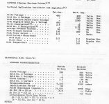
The recommended bias for the power section of 6AD10 is 8V. After some calculations and experimenting I found out the array of 8 lines x 5 leds fits the bill. It gives 8.71V drop with B+ of 290V and with the common cathode current of 69 mA - quite perfectly aligned. If one tube removed the current drops to 41 mA - not by half but relatively safe for one (the max current in specs is 39 mA, but these species are somewhat little stand-ups, and that won’t actually make a damage).
Here I want to mention why not a CCS. The output stage has the CCS in the original design, but I do not like a fact that the double current will run through a single bulb if one of two breaks or missing, and turns it towards garbage bin very quick if neglected.
Another my point is, well, we want it be biased at some constant, and the LED array works like a Zener here, except it has much lower dynamic impedance, hence no need of Blackgates caps )) to shunt the bias network. Do not try to waste blacks here as they would make a rather marginal difference, very opposite to resistive bias.
So for the LED array I opted for the DC-20/20/SRWA bar, hoping to get the consistency of the single LEDs and that turned out to be true. Much easier to mount as well.
The SHIII amp does not require any tuning up as long as you match the pairs, here is how. While having connected the only first stage’s networks - plug in any two and measure the plate voltages, mark them. You can get the range between 100 and 160 (Volts). It does not matter if the measurements were made with unmatching ones - the V value will remain close, you will see. Then just plug in whatever you found like 150 & 146 and 134 & 128 pairs and you are all set. Technically, I did not see any problem of having a pair of e.g. 121 & 152, they do work. The imbalance can be further fixed by adjusting the 10K resistor (I figured typically +/- 5K) by min of the 2 nd or the 3 rd HD, whichever you prefer.
The B+ value is not critical, the amp remains operational with the range of 200-300V, but 290V is the optimal.
The max output I got is 18V peak-to-peak, or 6.3V RMS (as by oscilloscope) on a 7.8 ohm dummy load.
I expected more, is it all I can get? suggestions are appreciated.
Enjoy.
I will post how it looks finished once I have it, might take some months ))
Oh, almost forgot! I have already modded the quite mates (I think) for SHIII, here is the process:

All this is just my modest beginner’s experience with vacuum tubes, sorry for any mistake made by misunderstanding of the concepts. (though I had had a quite extensive past with military electronics design, mostly low-powered circuits)
Some reading on 6AD10 applications:
Class AB2 - Kink, how and why?
http://www.diyaudio.com/forums/tubes-valves/216292-class-ab2-kink-how-why.html
Mini Gee-Tah amplifier, looong-time build
Mini Gee-Tah amplifier - UK Vintage Radio Repair and Restoration Discussion Forum
6AD10 datasheet
http://www.mif.pg.gda.pl/homepages/frank/sheets/123/6/6AD10A.pdf
Hi everybody, finally, after gathering myself and some parts I go up for a one.
The Dual-SE topology has been around for awhile:
Bel Canto SET 80 monoblock power amplifier | Stereophile.com
I got the idea to build it on 6AD10 compactrons and initially purchased a pair of ?USA? new-mades, those are with side getter and nice glow of filaments can be seen through the top. The supplier said they are made by Sylvania, had many of them in stock two months ago, but suddenly all batch got sold out before I inquired for another pair.
So I collected several old AD10s by GE, but I must tell it is hit-and-miss - I got two pairs out of 8, with two seem about worn out. Another option would be 6T10 (12T10) which is easier to get NOS:
5 Pcs National 12T10 Audio Radio Vacuum Tubes | eBay
Here is the schematics, very simple:
I have had it on breadboard for 3 days by now, and the first impression is not that awesome. The major advantage of DSE is the micro dynamics, m-m-m, appears (sounds) so. But the disadvantage of SE’s warming up delay kills whole impression. It takes up to 30-40 minutes for the amp to get to my-ear-acceptable sound quality.
I did not measure THD yet, could not get the Multi-Instrument software playing samples in the VM on MacBook, but with help of Spectrum Analyser the 2 nd could be eliminater to almost nil though the 3 rd remains at more or less constant level while adjustments.
I guess two things will improve its sound: the better power supply and the natural break-in. The chassis I’m gonna use does not have much space so the electronic chokes are intended.
The overall level of noise and hum is quite low even with no proper ground on the breadboard.
I’m a fan of LED bias, as you see. Some practical findings:
For the first stage the optimal bias turned out to be 2.1 V - it just sounds the best. I tried this variety of LEDs (none of superbrights): 1.65 (old red), 1.75-1.77 (modern red), 1.95 (modern red), 2.0 (old yellow), 2.07 (green), 2.1 (ancient led), 2.8 (blue), 3.45 (2 x red).
The best sounding one turned out the old crappy red one (2.1V) with glow barely seen. Same observation already noted by some forum members. Unfortunately I could not find a mate for it, so two of 2.07V greens will serve good enough.
For the output stage I opted for the LED array similar to "Redlights District" design:
The Red Light District: A 15W Push-Pull Amplifier
The recommended bias for the power section of 6AD10 is 8V. After some calculations and experimenting I found out the array of 8 lines x 5 leds fits the bill. It gives 8.71V drop with B+ of 290V and with the common cathode current of 69 mA - quite perfectly aligned. If one tube removed the current drops to 41 mA - not by half but relatively safe for one (the max current in specs is 39 mA, but these species are somewhat little stand-ups, and that won’t actually make a damage).
Here I want to mention why not a CCS. The output stage has the CCS in the original design, but I do not like a fact that the double current will run through a single bulb if one of two breaks or missing, and turns it towards garbage bin very quick if neglected.
Another my point is, well, we want it be biased at some constant, and the LED array works like a Zener here, except it has much lower dynamic impedance, hence no need of Blackgates caps )) to shunt the bias network. Do not try to waste blacks here as they would make a rather marginal difference, very opposite to resistive bias.
So for the LED array I opted for the DC-20/20/SRWA bar, hoping to get the consistency of the single LEDs and that turned out to be true. Much easier to mount as well.
The SHIII amp does not require any tuning up as long as you match the pairs, here is how. While having connected the only first stage’s networks - plug in any two and measure the plate voltages, mark them. You can get the range between 100 and 160 (Volts). It does not matter if the measurements were made with unmatching ones - the V value will remain close, you will see. Then just plug in whatever you found like 150 & 146 and 134 & 128 pairs and you are all set. Technically, I did not see any problem of having a pair of e.g. 121 & 152, they do work. The imbalance can be further fixed by adjusting the 10K resistor (I figured typically +/- 5K) by min of the 2 nd or the 3 rd HD, whichever you prefer.
The B+ value is not critical, the amp remains operational with the range of 200-300V, but 290V is the optimal.
The max output I got is 18V peak-to-peak, or 6.3V RMS (as by oscilloscope) on a 7.8 ohm dummy load.
I expected more, is it all I can get? suggestions are appreciated.
Enjoy.
I will post how it looks finished once I have it, might take some months ))
Oh, almost forgot! I have already modded the quite mates (I think) for SHIII, here is the process:
All this is just my modest beginner’s experience with vacuum tubes, sorry for any mistake made by misunderstanding of the concepts. (though I had had a quite extensive past with military electronics design, mostly low-powered circuits)
Some reading on 6AD10 applications:
Class AB2 - Kink, how and why?
http://www.diyaudio.com/forums/tubes-valves/216292-class-ab2-kink-how-why.html
Mini Gee-Tah amplifier, looong-time build
Mini Gee-Tah amplifier - UK Vintage Radio Repair and Restoration Discussion Forum
6AD10 datasheet
http://www.mif.pg.gda.pl/homepages/frank/sheets/123/6/6AD10A.pdf
Last edited by a moderator:
The max output I got is 18V peak-to-peak, or 6.3V RMS (as by oscilloscope) on a 7.8 ohm dummy load. I expected more, is it all I can get?
You have essentially paralleled the output windings, so each output tube sees nearly 10K load instead of 5K with your 7.8 ohm test load. Is that what you planned for?
had many of them in stock two months ago, but suddenly all batch got sold out before I inquired for another pair.
It seems that someone in Hong Kong snaps up ALL of the tubes available if they get talked about on this, or any of the popular audio forums. This practice will kill off all new innovation in tube audio if it continues. I have designed two new audio amps using tubes that were in abundant supply (over 10,000 in stock at two suppliers) only to have all the tubes disappear overnight. Yes, 10,000 6HB6's were snapped up from a single supplier by a single buyer in Hong Kong who "buys $50K to $150K USD" tubes from him a year. I haven't started a new tube amp design since then, and am currently working on something totally different.
the design I got is rather good for 4 ohm load
Try it. Assuming you don't have similar speakers in 4 ohm, or 4 speakers, listen to one channel with one speaker, then parallel the second speaker on the same channel. Does the amp sound better, or worse.
You might find that you make more power on a 4 ohm load, but the amp sounds better with an 8 ohm load. The 4 ohm load will have about half the damping factor, and probably a bit higher distortion.
Yep. .. these niceones, got them just one pair, if anybody wants they are avail:
I thought about the 8 ohm load better sounding, just do not have a 4 ohm speaker around and paralleling does not sound the right thing to do, well will try. 6.3 RMS is what, like 5 watts? I got one channel yet, but it is quite loud at max, though listen-able on maybe 2/3.
An externally hosted image should be here but it was not working when we last tested it.
I thought about the 8 ohm load better sounding, just do not have a 4 ohm speaker around and paralleling does not sound the right thing to do, well will try. 6.3 RMS is what, like 5 watts? I got one channel yet, but it is quite loud at max, though listen-able on maybe 2/3.
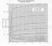
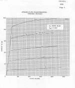
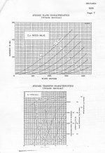
Section 2 of the 6AD10, the input pentode, will work a lot better if you put +4 Volts on grid3 (with respect to the cathode). Check datasheet (bottom of page 5). Makes the plate curves square up. You may have to lower the 51K plate load resistors then, due to more plate current. (0 Volts on grid3, WRT cathode, gives the awful plate curves at top of page 6)
Last edited:
Can that be achieved with a small 6.2 V zener (as I have ~2.1 V on S2's cathodes) fed from B+? I guess the 3 rd grid current should be tiny.
Thanks for the valuable input - that kind of tricks I gotta learn.
Well, at "as is" I got the sensitivity about 0.9 V to max output, which is perfect for what I intend it to use. If "squared", I guess, the sensitivity will raise a bit - not what I'm looking for.
I am more interested in better linearity.
I would guess that using +6.2V grid3 boost would work fine. I have a 12BV11 tube here with a similar dual control pentode inside. It reaches maximum plate curve squareness at +12.5V on grid3. It has half the grid3 gm of the 6AD10, so likely half that V, or +6.2V, would give max squareness for the 6AD10.
Squaring up the plate curves should improve the linearity.
6AD10 at $7 or $8 doesn't seem too likely to get bought up in quantity. I did find it listed on the 2003 AES bargain sheet for $1, but not any other years. Probably not that plentiful. Miss that treasure hunting era. 6T10 is on the $1 list still. Was $0.50 on the 2002 AES bargain list.
12HE7 and 38HE7 have a nice power pentode in them, along with a useless damper diode. Still on the $1 list. The 38HE7 usually has the heater for the pentode alone available on pins 10 and 12 at 21V. That allows the pentode to run at up to around 15 Watts max. Pdiss then.
Last edited:
There is something wrong with this circuit 
Schade feedback doesn't go together with this kind of fase inverter.
You get hum and other undesirables from the power supply in the output.
Unwanted noises from the power supply gets to the grid of the final stage.That same signal is inverted and fed to the other grid, canseling the same noise from the supply.Result is an uneaqual hum on the symetrical power amp, it isn't cancel out any more.
I sugest an other fase inverter, like this.
Mona
Attachments
You mean 200K resistors from output stage plates?
I made it without them first. It was more noise, louder hum, a little more distortion. The gain was excessive to what I need, the sensitivity was 0.3V to full output.
Adding 200K resistors made, I would call, an improvement.
I made it without them first. It was more noise, louder hum, a little more distortion. The gain was excessive to what I need, the sensitivity was 0.3V to full output.
Adding 200K resistors made, I would call, an improvement.
Oh, I didn't notice the 1K resistors from plates to grid2 of the input tubes before. So they are running in triode mode. The +6V boost on grid3 won't make any difference then.
Wiring the input tubes as pentodes is the usual practice for a Schade type plate feedback (for output tubes). Some RC de-coupling from B+ for the input tube plate resistors might help. But Schade feedback is still referenced to B+. Unavoidable hum, unless one puts some P-channel Mosfets up top to send current only down to the grids. Another approach is to put the OT secondaries in the output tube cathode circuits, CFB, then send feedbacks from the output cathodes back to the driver cathodes via resistors (crossed).
Wiring the input tubes as pentodes is the usual practice for a Schade type plate feedback (for output tubes). Some RC de-coupling from B+ for the input tube plate resistors might help. But Schade feedback is still referenced to B+. Unavoidable hum, unless one puts some P-channel Mosfets up top to send current only down to the grids. Another approach is to put the OT secondaries in the output tube cathode circuits, CFB, then send feedbacks from the output cathodes back to the driver cathodes via resistors (crossed).
Last edited:
"I am more interested in better linearity."
The triode configured input tubes may be the main cause of the non-linearity. The triode Rp varies with current, yet it is part of the divider network for the Schade Fdbk resistors. Could put Mosfet followers, with a series resistor, after the 1st tube stages.
Or crank up the idle current for the triodes so Rp is more constant. Not a good choice with dual control pentodes however, since most of the cathode current gets returned to grid2. (unless you put the +6V on grid3 to fix that)
----
"---horde of tubes that can be snapped up by the Hong Kong buyer."
I notice the 12HL7s on the $1 list are gone now. There is one odd tube on the list, 17H-B25, a magnoval base Japanese Sweep tube. No data anywhere. Looks similar to the 13GB5s (which also disappeared, along with the 6HB6s, 6LU8s, 6AV5s, 6FW5s, 29GK6s, 12GE5s, 21HB5s, 17KV6s ...). Any info out there? Last one.
..
Last edited:
Thanks, guys, for valuable input.
Ketje, the suggested phase invertor works well. I adjusted the 1K2 to + 200, and it sounds cleaner and aery. The voltage drop over BC547 (I used 2SC945) is 2.05V.
You left just one, but I assume both 220K resistors in power sections' grids are necessary.
Yeah, the B+ decoupling for the first stage will be made with a common choke for both channels.
I tried 2 speakers on a channel i.e. 4 ohm load, sounds much better in the way that there are two – more output etc. To make the more appropriate comparison “with a single speaker” I shunted it with that 7.8 ohm resistor.
With 4 ohm load I get the volume slightly quieter and the sound slightly “dull” with less HF and LF.
So it seems yes, gotta replace the trafos with either 16 ohm secondaries or ~3K primaries.
These XSE10-8-5K pairs otherwise are great for 4 ohm load, with two speakers in parallel they get barely warn but the impression is I get is close to 8 Wa (as the AD10’s specs say the max is 4.2 Wa in A-class SE), have not measured though.
Another given suggestion is to add some winding to the secondary, and, with care, it seems doable. There is a gap big enough to put one more layer + the coil top insulation can be removed. I will find out the ratio numbers and give it a try, ordering the new trafos might take up to 10 weeks. I have no idea where to locally buy the enameled copper wire of certain gauge in small amount, can you guys advise any online source?
smoking-amp, I get your point, would try +6V on grid3 but tell me what I do with grd2 then? sorry I am not advanced with tubes. Tnx.
Oh yes, sorry I forgot to place that back.
The hum you can get with the original circuit doen't come from the supply of the first stage.It comes in via the Schade feedback resistors.
With the transistor the circuit is symetric and hum on the supply is allmost canceled out.
The 1k at the transistor was to get ~130V on the anodes, now you have 10...15V less I suppose.If that sounds ok, why not.
Mona
0V on g3 repels a significant portion of the cathode/plate current back to grid2 (6AD10 input, tube section 2), causing the rounded plate curves on the datasheet. Putting +6V on g3 lets most of it get through to the plate.
For triode mode, you could just connect the g3 to the g2 of each input tube as currently done.
I just noticed that 6MF8 is on the $1 list now. Another tube you could try out, that has a normal driver triode. Although a rather different pin-out. Not that it is any better than 6AD10A. (same as 6LU8 pinout) Data: (6MF8 output stage has 2/3 the gm, but input triode has 1.5X the gm of 6AD10A)
Summer Dollar Days - Vacuum Tube Sale - $1.00 Vacuum Tubes
https://frank.pocnet.net/sheets/084/6/6MF8.pdf
Attachments
Last edited:
I see now, tnx for explanation and for suggestion on 6MF8. I am kind of happy with 2 good pairs of AD10 that I already have.
As Mona pointed out that would be not good to Schade FB so I guess I remove two 200K resistors. What I was asking: if I make the g3 biased with +6V then do I keep g2 connected to the plate?
As Mona pointed out that would be not good to Schade FB so I guess I remove two 200K resistors. What I was asking: if I make the g3 biased with +6V then do I keep g2 connected to the plate?
Connect input stage g2 to the plates for triode mode as existing with series resistor. (with g3 connected to g2)
Otherwise, fix +g2 voltage as a screen grid for pentode mode. Might have to put some degeneration resistors under the cathodes in pentode mode to linearize the Vin to Iout transfer. CCS tail can stay in.
Sound-wise, you would have to trial them. Some will say the pentode input mode is more appropriate for Schaded outputs due to the current drive into a low impedance node, but RH amplifiers using triodes seem to be well liked. Some operating point tweaking no doubt important.
I think Mona was saying that the hum coming in on the 200K Fdbk resistors would cancel out in the P-P output now that there is a CCS tail. (equal hum on each phase cancels out ) So I would leave those 200K resistors in.
Last edited:
s-a, I tied your suggestion on pentode mode.
Sound-wise it is not bad, on my taste sounds better than CCS tail,
Your otherwise assumption of cranking up the current in triode is right, the amp tends to sound better if so.
In pentode I got both valves' g3 connected to a common 6V zener (with electrolytic), and each g2 has an individual network of 220K + 0.22uF cap to the ground (btw, would the caps better be connected to cathode(s)?)
Each g2 has the recommended 100V, and 0.8mA seems just right, but. . . the plates now get ~215V. If I try to bring the plate down to e.g. 150 by decreasing the cathode resistor I get almost no change. Instead, the g2 voltage varies quite a bit, could go down 70 or even 50V.
Is that normal?
For this (same, I guess) reason the CCS tail does not work here, it forces the drop over the cathode resistor down to 0.075V (instead of 2V sweet-spot)
Schade NFB sounds a great improvement. It halves the sensitivity but makes the amp better balanced by giving it fat bass.
- - - - -
Ketje, that divider on the out of the leftmost V1a valve was not a mistake. Though looking wrong it sounds quite sweet, better than V2a's g1 reference to just ground. If to ground - the sound is rather towards silicone. With that divider I get 3 rd HD almost disappear on 5V RMS, plus it gives approx. 30% boost.
That divider gives V2a the signal+ hum from anode and Schade resistors to make the inverted fase.
With a CCS in the cathodes the signal commes in via the cathode of V2a, no extra hum.
The transistor of the CCS pulls the cathode down until -Vg1 is right for the anode current to give the proper anode voltage (drop on the anode resistance)
If Vg2 is to low to even get the nessesairy anode current at Vg1=0V the transistor goes in full conductivity in an effort to turn up the current.
Mona
- Status
- This old topic is closed. If you want to reopen this topic, contact a moderator using the "Report Post" button.
- Home
- Amplifiers
- Tubes / Valves
- SHIII project, All-Pentode PP