Many moons ago I was asked to rebuild a pair of rather used and abused Eico HF-60 monoblocks.
Schematic Here
These amplifiers, however, were not stock; each one had a AA battery supplying the bias on the input tube. Now here is the background to my question - I recently had a conversation with the previous owner (who has since sold them) who said the battery was in series with the cathode/ground, with the feedback loop from the output coupled to the cathode via a .22uF capacitor. This approach doesn't make any sense to me once feedback in introduced.
I remember the amps differently - negative voltage from the battery going to the grid, the .22uf cap acting as a DC blocker after the volume control. Feedback attached to the remaining 100ohm resistor on the cathode. (see schematic for details).
So - finally! - here is the question: With battery bias on an input tube, and loop feedback, what is the best way to apply the feedback?
Sorry for the vague-ish details. If need be I can draw out the two different scenarios.
Last edited:
The stock schematic is a rather nice Mullard circuit. The 6SN7 makes an excellent LTP phase splitter.
If battery bias was used in the g1 circuitry of the EF86, a DC block would be needed there. Also, the 50 muF./1.6 Kohm bias network would have to be eliminated. A 0.22 uF. cap. combines with 1 Mohm of resistance to produce a high pass pole whose F3 is 0.72 Hz.
The stock 50 muF./1.6 Kohm bias network yields an approx. 2 ohm high pass pole. IMO, there's no significant difference in the 2 "corner" freqencies.
Attachments
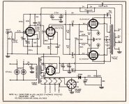
I may be wrong but if a battery is used, it should go between cathode and ground. An EF86 cannot work with that much positive voltage on the grid and only 100R in the cathode. There will be no anode voltage left. If the battery went where the 1k6 resistor is, that would work but no advantage as far as I can see.
Jon,
As long as g1 is correctly negative with respect to the cathode, all is well. In the grid circuit, the positive terminal of the bias battery is grounded. It's quite similar to the "fixed" bias O/P stages that are commonplace.
You can use a battery between cathode and ground, providing it is rechargeable (like NiMH or NiCd). Then, the trickle of current keeps the battery charged. A trickle through carbon/zinc or alkaline could be trouble. Given the tiny cathode current of an EF86, battery bias in the grid circuit is (IMO) the way to go.
Last edited:
Jon,
As long as g1 is correctly negative with respect to the cathode, all is well. In the grid circuit, the positive terminal of the bias battery is grounded. It's quite similar to the "fixed" bias O/P stages that are commonplace.
.
With a battery source you would still have to feed the voltage to the grid through the appropriate grid resistor. The internal resistance of an alkaline battery is @ 0.15R. Fixed bias is fed in through a resistance so the signal isn't killed. The battery would bypass the grid if it was just the battery in the ground path.
I would be pretty careful about putting a bias cell in series with the grid stopper because of the possibility of stray coupling. A tiny hearing-aid cell might help in this situation.
This is just an idea: Perhaps a photovoltaic optocoupler could be used instead of a primary cell. It may be possible to derive low bias voltages as a difference between two low-voltage zeners, for instance, which would overcome most of the disadvantages of this approach.
This is just an idea: Perhaps a photovoltaic optocoupler could be used instead of a primary cell. It may be possible to derive low bias voltages as a difference between two low-voltage zeners, for instance, which would overcome most of the disadvantages of this approach.
Last edited:
...... who said the battery was in series with the cathode/ground, with the feedback loop from the output coupled to the cathode via a .22uF capacitor.
If taken literally, that means that the 100 ohm resistor is no longer in the cathode-ground circuit? Hopefully what was meant was that the battery is in series with the cathode - 100 ohm resistor, i.e. in place of the 1,6K resistor, as it were. Without the 100 ohms and a good battery the EF86 cathode is ac-shorted to ground; there would then no longer be any NFB. And a battery used as a current sink? Have never seen data on that vs. battery life.
(Apart from the fact that it makes no sense to have a battery anywhere - but not all the details were given for such a step.)
If taken literally, that means that the 100 ohm resistor is no longer in the cathode-ground circuit? Hopefully what was meant was that the battery is in series with the cathode - 100 ohm resistor, i.e. in place of the 1,6K resistor, as it were. Without the 100 ohms and a good battery the EF86 cathode is ac-shorted to ground; there would then no longer be any NFB. And a battery used as a current sink? Have never seen data on that vs. battery life. p.)
That was my thought too - just trying to make sure I wasn't nuts. Again, it isn't important but more of a theoretical question.
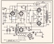
I've uploaded a tweaked schematic that uses battery bias.
Thanks, Eli - that's close to how I remember it.
- Status
- This old topic is closed. If you want to reopen this topic, contact a moderator using the "Report Post" button.
- Home
- Amplifiers
- Tubes / Valves
- Battery bias and negative feedback