Hi, I'm back again. My 600 Ohm Resistors arrived today, but then I thought, in my basic test for class a, I have not disproved that it isn't class a. So unless anyone can suggest a more definitive test, I'll have to presume it is class a and leave original common resistor. Only problem is, do I remove the 100uF capacitor?
Hi, I am reworking a Cathode Biased KT88 Amplifier. I have only discovered this mode of operation since picking this amplifier up. It uses 2 x KT88s Per Channel. Presently it uses a single 300 ohm resistor,bypassed with a 100uF capacitor. I have been reading various articles about configuration and it appears the general consensus is separate resistor/capacitors for each cathode is the way to go. I would think to keep the status quo, I would use a 600 ohm resistor for each cathode? But not sure about capacitor. Been advised elsewhere to increase value. Not 100% with this. Any advice would be very much appreciated. Some basic measurements I have taken. Anode to Cathode 420, voltage drop across the 300 ohm resistor 42.
Any advice greatly appreciated.
I would advise ditching cathode bias altogether and go with fixed bias. If you're not gonna do this, then separate cathode bias resistors will help with DC offset. With a common cathode resistor per PP pair, you really need to match the tubes for DC to ensure you're not getting a nasty DC offset that can lead to excessive core magnetization (bad for sonic performance).
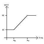
As for how to select bypass capacitors, see the Bode plot here. This is a shelving filter. The zero is: w0= 1/(CKRK)
The pole is wp= 1/[(rk || RK)C]
For a pentode, rk~= 1/gm
You could also go for the usual bypass sizing: XC= 0.1RK at the lowest frequency of interest. This is likely to produce "high side" errors, but also make sure by checking the actual break points to be sure they're well away from the low end of the audio band.
Attachments
Hi Miles, thanks for reply. I did consider changing to fixed bias, but decided against it on cost and time grounds.I am also not sure from reading across platforms whether fixed bias has any sound performance benefits over Cathode Bias.
I was under impression that if it was class A, that a common resistor was the norm, with no bypass capacitor.
I was under impression that if it was class A, that a common resistor was the norm, with no bypass capacitor.
Class A permits, but does not require, a common cathode resistor. I would not describe it as the norm, but it is certainly not rare. Most amps probably use two separate resistors, as that copes better with valve matching and ageing. A common resistor may help balance, and so slightly reduce even order distortion.
Hi DF, I'm trying to get my head round this. If the tubes have separate resistors and capacitors, wouldn't that mean that at the cathode junctions there would have different charge/discharge rates which would cause inferior ac performance. As against a single resistor forcing a summing effect, therefore DC bias would be held constant,although the tubes may not actually be contributing equally. I'm sort of thinking out loud, hope you get my drift?
The capacitor, if it is big enough, maintains a constant voltage. I don't know what you mean by "inferior ac performance". The cap voltage could be more constant than that on a common resistor.
The dominant distortion in the output valves will be second-order. This causes a rise in average current with signal. A common resistor will see a rise in voltage (with second harmonic too). A sufficiently big cap will suppress this, at least for brief transients.
The dominant distortion in the output valves will be second-order. This causes a rise in average current with signal. A common resistor will see a rise in voltage (with second harmonic too). A sufficiently big cap will suppress this, at least for brief transients.
Hi DF, I'm kind of looking at the cathodes in this configuration as being flexible 0 volts, so if both cathode get tied to a common resistor or resistor/capacitor combination, the voltage will remain constant between both tubes cathode and anodes. If they have separate resistors or resistor/capacitors, then that could mean the difference in HT between anodes and cathodes would loose their forced symmetry and in the case of capacitor bypassing, also have potential to cause pulses from delayed discharge from capacitors on either leg, which could impact on its audio(ac) performance.
When signal is present the two anodes no longer have the same voltage anyway. The extra symmetry from having a common unbypassed cathode resistor is because it acts as a very poor tail in a very short long-tailed pair. Nothing to do with anode voltage.
Capacitors will delay voltage changes; that is what they are there for.
Anyway, a common resistor gives better AC balance. Separate bypassed resistors give better DC balance. I think the latter is more important as that naturally leads to good AC balance too.
Capacitors will delay voltage changes; that is what they are there for.
Anyway, a common resistor gives better AC balance. Separate bypassed resistors give better DC balance. I think the latter is more important as that naturally leads to good AC balance too.
OK, thanks for bearing with me. I'll go for separate cathode resistors. I've got some nice 680uF 100 Volt capacitors, do you think they will be OK for bypass caps?
Yes, anything from about 220uF to 1000uF will do.
- Status
- This old topic is closed. If you want to reopen this topic, contact a moderator using the "Report Post" button.
- Home
- Amplifiers
- Tubes / Valves
- Cathode Bias Resistor and Capacitor Values