Flush off a recent success with a mainstream tube amp (12AX7/6AQ5), I decided to rummage through my tube stash and see what oddity I could find to offend and delight my senses.
[NOTE: I'm a newbie. I can solder and use a DMM and read a schematic, and that's about it. Please be gentle.") ]
]
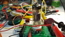
I came up with a quad of GE NOS 10LY8 tubes. They are nice little fat-bottle Novar tubes that appear to be a high-mu triode and a sharp-cutoff pentode in one bottle. Not that unusual, I guess, except for the heater voltage. But a quick search through Google didn't seem to turn up anyone doing anything fun with them, except for a mention here and there.
http://www.nj7p.info/Tubes/PDFs/Frank/135-GE/6LY8.pdf
http://tubedata.itchurch.org/sheets/191/6/6LU8.pdf
The heater is a 10.5 volt unit drawing 450ma. I took a 12.6 VAC 3a transformer and fed it into one of those el cheapo eBay voltage regulators, giving me 10.5 volts DC on the heater, no problem.
The PT I am using for this experiment puts out 285 VAC, and I put it through a SS bridge rectifier and then CRCRC smoothing, putting out about 340 VDC without load.
The triode unit is high-mu, with an amplification factor of 100. I don't know what I'm doing, so I treated it like a 12AX7 and put a 100K resistor on the plate and 1.2K resistor on the cathode. For now, I did not bypass the cathode resistor, I figured I could do that later. I also did not use a grid stopper or a grid leak resistor. Figure I need them but since I was just messing about, I left them off for now.
I used a .01uF 630V film capacitor in front of my signal input as well as from the plate of the triode unit to G1 of the pentode side. G3 is internally connected to the cathode, and I strapped G2 to the plate with a 330 ohm resistor. Not sure if that was smart, but I did it. I used a 620 ohm cathode resistor on the pentode unit.
How did I decide what values to use for cathode on the pentode side? I just took a wild stab at it. I have no clue what I'm doing here.
I used an AES P-T31 output transformer. It's rated at 5 watts, 5K primary to 8 ohm secondary.
Well, that was simple. I fired it up.
Voltage on the pentode plate seemed to stabilize at 300 volts, but voltage on the triode plate registered 720 volts for five or 10 seconds, until the heater decided to warm up, then it dropped to about 300 volts as well. I'm guessing that was a terrible awful evil thing for me to have done. Any ideas how I managed that one and what I could do to avoid it in future?
After the extended heater warmup, I started getting sound right away. Some distortion, can't say it sounded great, but it made music. A bit of hum, but nothing horrible.
However, the plate voltages did not get stable. I expected them to settle down, but they kept jumping up and down by 20 to 40 volts. Clearly affected the sound as well.
I was going to measure the voltages at the cathodes, but I decided to come here, post my results, and await my flogging.
I know I've been naughty, but how bad is it, doctor?
[NOTE: I'm a newbie. I can solder and use a DMM and read a schematic, and that's about it. Please be gentle.
]I came up with a quad of GE NOS 10LY8 tubes. They are nice little fat-bottle Novar tubes that appear to be a high-mu triode and a sharp-cutoff pentode in one bottle. Not that unusual, I guess, except for the heater voltage. But a quick search through Google didn't seem to turn up anyone doing anything fun with them, except for a mention here and there.
http://www.nj7p.info/Tubes/PDFs/Frank/135-GE/6LY8.pdf
http://tubedata.itchurch.org/sheets/191/6/6LU8.pdf
The heater is a 10.5 volt unit drawing 450ma. I took a 12.6 VAC 3a transformer and fed it into one of those el cheapo eBay voltage regulators, giving me 10.5 volts DC on the heater, no problem.
The PT I am using for this experiment puts out 285 VAC, and I put it through a SS bridge rectifier and then CRCRC smoothing, putting out about 340 VDC without load.
The triode unit is high-mu, with an amplification factor of 100. I don't know what I'm doing, so I treated it like a 12AX7 and put a 100K resistor on the plate and 1.2K resistor on the cathode. For now, I did not bypass the cathode resistor, I figured I could do that later. I also did not use a grid stopper or a grid leak resistor. Figure I need them but since I was just messing about, I left them off for now.
I used a .01uF 630V film capacitor in front of my signal input as well as from the plate of the triode unit to G1 of the pentode side. G3 is internally connected to the cathode, and I strapped G2 to the plate with a 330 ohm resistor. Not sure if that was smart, but I did it. I used a 620 ohm cathode resistor on the pentode unit.
How did I decide what values to use for cathode on the pentode side? I just took a wild stab at it. I have no clue what I'm doing here.
I used an AES P-T31 output transformer. It's rated at 5 watts, 5K primary to 8 ohm secondary.
Well, that was simple. I fired it up.
Voltage on the pentode plate seemed to stabilize at 300 volts, but voltage on the triode plate registered 720 volts for five or 10 seconds, until the heater decided to warm up, then it dropped to about 300 volts as well. I'm guessing that was a terrible awful evil thing for me to have done. Any ideas how I managed that one and what I could do to avoid it in future?
After the extended heater warmup, I started getting sound right away. Some distortion, can't say it sounded great, but it made music. A bit of hum, but nothing horrible.
However, the plate voltages did not get stable. I expected them to settle down, but they kept jumping up and down by 20 to 40 volts. Clearly affected the sound as well.
I was going to measure the voltages at the cathodes, but I decided to come here, post my results, and await my flogging.
I know I've been naughty, but how bad is it, doctor?
Attachments
You said no grid leak resistor on the high mu triode and yet you are AC coupled to the source? You need that resistor to establish a dc path for the minute amount of grid current that flows - I'd use a 1M resistor to gnd, and I hope you have one on the pentode as well - what value cathode resistor and cap are you using on the pentode? (Edit: I see 620, probably something on the order of 220 - 270 ohms bypassed by 100uF would be better. Need a => 2W resistor here for safety)
Something funky with your meter, you can't have more voltage on the plate than the supply is putting out. (What is the initial value and the warmed up value?
Please post a schematic, even hand drawn with a phone snap shot would be helpful.
Something funky with your meter, you can't have more voltage on the plate than the supply is putting out. (What is the initial value and the warmed up value?
Please post a schematic, even hand drawn with a phone snap shot would be helpful.
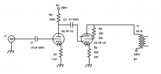
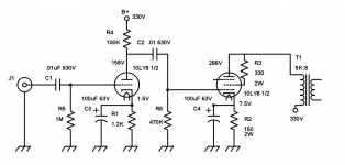
OK, so here is the schema as it exists right now.
Please note that on the pentode half of the drawing, G3 is internally connected to the cathode at pin 6. I was unable to make the editing software show this for some reason.
I understand that I need to add a grid leak resistor of 1 meg from the grid of the triode to ground. I need to change the cathode resistor value from 620 to 220, 2 watts. I need a grid leak resistor on the grid of pentode section, probably about what, 470K?
And I need to bypass the cathode resistors with a 100uF electrolytic.
I will make those changes, then test, take voltage measurements, and modify the schematic and report back.
Thanks!
Attachments
So I have followed the instructions, or at least I think I have. Unfortunately, now the amp sounds much worse, although the voltages are stable and not swinging wildly around.
B+ at the pentode plate measures 280V and is stable.
B+ at the triode plate measures 150V and is also stable (no more weird 750+ voltage readings).
I am measuring 8 volts at the pentode cathode.
I am measuring 1.5 volts at the triode cathode.
These all sound like sane values to me, something I would expect to see.
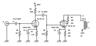
I added a 1M grid leak resistor at the triode grid, and a 470K grid leak resistor at the pentode grid. I changed the pentode cathode resistor from 620 Ohm to 220 Ohm, 2 watts. I bypassed both cathode resistors with 100uF 63V electrolytic capacitors.
The sound is now almost non-existent. With volume turned to max, I barely hear a whisper, and what I hear is highly static-y.
Any thoughts?
Here is the updated schematic with the changes I made.
B+ at the pentode plate measures 280V and is stable.
B+ at the triode plate measures 150V and is also stable (no more weird 750+ voltage readings).
I am measuring 8 volts at the pentode cathode.
I am measuring 1.5 volts at the triode cathode.
These all sound like sane values to me, something I would expect to see.
I added a 1M grid leak resistor at the triode grid, and a 470K grid leak resistor at the pentode grid. I changed the pentode cathode resistor from 620 Ohm to 220 Ohm, 2 watts. I bypassed both cathode resistors with 100uF 63V electrolytic capacitors.
The sound is now almost non-existent. With volume turned to max, I barely hear a whisper, and what I hear is highly static-y.
Any thoughts?
Here is the updated schematic with the changes I made.
Attachments
Thanks to both of you, the problem was indeed me; or rather, a bad 9-pin socket. It appears that one of the internal pin-holders had bent back on itself and the pin was not making fully contact when the tube was inserted. I replaced the socket and everything sprang to life.
I am including a new and updated schematic. I replaced the pentode cathode resistor with a 150 Ohm 2 watt resistor as recommended.
The sound quality is excellent - I have no way of measuring, but it sounds 'clean' to me and it also sounds somewhat louder than a typical 1 watt amp (I have several, and this sounds definitely louder). There is a bit of distortion at top volume.
I am considering using feedback - suggestions?
Thanks again for all your help (both of you). I am quite pleased with the way this little toy turned out.
Attachments
One final thing, check plate dissipation in the output stage, if too high you might need to back off a bit. The dissipation if your measurements are correct appears to be about 14W which is way too much having looked it up. The pentode is rated at 5W... Plate voltage is also perhaps a bit too high - 250V seems closer to the mark.
Data sheet here: http://www.mif.pg.gda.pl/homepages/frank/sheets/191/6/6LU8.pdf (It follows the 6LU8 in the data sheet.)
I would change the cathode resistor to 330 ohms, but you might get away with a little more dissipation so I would experiment.
Data sheet here: http://www.mif.pg.gda.pl/homepages/frank/sheets/191/6/6LU8.pdf (It follows the 6LU8 in the data sheet.)
I would change the cathode resistor to 330 ohms, but you might get away with a little more dissipation so I would experiment.
the 6lu8 is a nice sounding tube, got a bunch of them for a dollar each at Rogalski's many years ago, now they sell for 4 american dollars each...
there are many triode pentode combinations out there that you use, like the 11bm8 and such...
I happen to have some NOS 21LR8 and 21LU8 tubes that I will one day soon build with, as well as a pair of 6T9. I've already built one 6T9 SE amp.
But I've always used other people's schematics. For this 11LY8, I had to try to figure it out myself.
I happen to have some NOS 21LR8 and 21LU8 tubes that I will one day soon build with, as well as a pair of 6T9. I've already built one 6T9 SE amp.
But I've always used other people's schematics. For this 11LY8, I had to try to figure it out myself.
no shame in that, using other people's scheme......
but you have to understand how it works,
the 6lr8 and the 6lu8 and heater variants are the same tube although different bases...
i made several amps out of the 6lu8 and worked nicely each time...
Attachments
I estimate input stage gain at ~65 with C3 in place. That's about 8~9 times what you need to drive the final stage to full output, so there's plenty of gain available for feedback. One way to do this is to lift C3 and R1 from ground, tie their previously grounded ends, then insert a small resistor (e.g. 47R) between that node and ground. Call it R7. Add another resistor, R8, from the same node to OPT secondary high side. OPT secondary low side must be grounded. Starting with R8 around 20~50 times the value of R7, work the value of R8 down incrementally and confirm that gain reduces with additional feedback. If oscillation commences immediately, reverse OPT primary or secondary connections (not both). Oscillation is inevitable as R8 is reduced to only several times the value of R7, but perhaps you will find a Goldilocks zone where the amp is stable and sonics are improved. If you want to progress beyond this approach, then it's time to consider investing in a scope and squarewave generator.
- Status
- This old topic is closed. If you want to reopen this topic, contact a moderator using the "Report Post" button.
- Home
- Amplifiers
- Tubes / Valves
- Forgive Me DIY Audio, For I Have Sinned 10LY8