Hi,
I am looking for a bit of guidance in regard to a tube preamp kit and what appears to be a miss match in terms of the parts. Particularly, the schematic references transformer secondary taps of 3.15v, 6.3v and 230v.
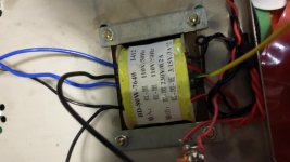
The photo of the transformer that came in the box is plainly missing the 6.3v tap. So my question is twofold. Can I leverage to needed 6.3 volts by some wiring slight of hand? Alternately, how much wiggle room do I have if I buy a replacement transformer that does not quite match. For example, I have found a few with 230 volt, 6.3 and 6.3 taps, so I would assume that I could alter the resistors and caps until I reach the expected voltage as designed.
Thanks in advance.
I am looking for a bit of guidance in regard to a tube preamp kit and what appears to be a miss match in terms of the parts. Particularly, the schematic references transformer secondary taps of 3.15v, 6.3v and 230v.
The photo of the transformer that came in the box is plainly missing the 6.3v tap. So my question is twofold. Can I leverage to needed 6.3 volts by some wiring slight of hand? Alternately, how much wiggle room do I have if I buy a replacement transformer that does not quite match. For example, I have found a few with 230 volt, 6.3 and 6.3 taps, so I would assume that I could alter the resistors and caps until I reach the expected voltage as designed.
Thanks in advance.
Attachments
Like this ?Thanks,
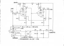
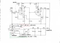
Still a bit fuzzy though as I don't readily understand how the 6z5p pins 2 & 7 relate to the 6j4 pin 3 & 4 with the 6p6p pins 2 & 7?
are they all on the same tap?
...gotta study this a bit closer
Mona
Attachments
Thanks to everyone thus far,
Your digram makes perfect sense, but....
Maybe I'm built too low and the fast ones keep going over my head? In Ketje's diagram, the 6z5p pins 2 and 7 are shown to be connected to a 6.3 tap. Seeing as my transformer does not have that tap, how do I realize the connection with the two taps that I have?
In the mean time I will map out how I decipher everyone's combined input so far and continue to monitor.
I really appreciate everyone's time!
You may connect all heaters on the same 6.3V winding.The cathode of the rectifier tube is isolated, no conflict.And the 3A is ok for 2x 6J4 + 2x 6P6P + 6Z5.
Most manufacturers do it also like that, I don't like it much.If the rectifiers get shorted the other tubes suffer too.
Mona
Most manufacturers do it also like that, I don't like it much.If the rectifiers get shorted the other tubes suffer too.
Mona
Newb2toobs, I believe the schematic is simply showing an error. Use the transformer's 3.15v-CT-3.15v output to feed all 3 filaments in parallel from two 3.15v taps and ground the CT. Thus, ignoring the non-existance of a 6.3 winding as shown on the schematic. The designer likely used a transformer drawing he had from an earlier project. Connect the rest of the transformer as shown. The 3amp capability of the heater winding you will be using is more than enough for your three tubes.
Mickeystan
Mickeystan
- Status
- This old topic is closed. If you want to reopen this topic, contact a moderator using the "Report Post" button.
- Home
- Amplifiers
- Tubes / Valves
- Transformer taps