Probably at least 5H or so. Hammond is ok, but try and get vintage stuff if you can.
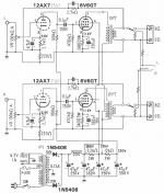
This circuit is cool, I like the design, but you could probably try some negtive feedback. Attach a 4.7K resistor from the 8 ohm tap on each output tranny to the junction of the 2.7K and the 220 ohm resistor. If it oscillates, then swap the output transformer terminals around.
Also you could try replacing the 2 silicon diodes in the power supply with a tube rectifier, say an EZ81; or 5V4 if you have a spare 5V winding.
rvas18 said:what size choke do i need for this schematic
There are only two sources of information on how to use chokes. One is to find an electronics engineering handbook from 50 or more years ago. The other is a free download from On Semiconductor:
http://www.onsemi.com/pub/Collateral/HB214-D.PDF
This actually has more information on chokes than any other resource I've found.
Best regards,
Charles Hansen
what size choke do i need for this schematic, and are there other sources for chokes than Hammond?
2.75H is critical inductance, 5.5H would be optimum, 5H would be ok, 10H-20H would be better.
John
Hi,
The schematic shows model SA-6302 from the Company San-ei that sells tube amplifier kits http://www2.ocn.ne.jp/~san-ei/index.html the SA6302 model is quite old and not sold anymore, (the company closed down the shop in Tokyo when Tango stopped making transformers but the company has since re-opened as mail order only). All older San-ei amps used only Tango parts for chokes, power transformers and output transformers so the choke in the diagram is a Tango part. I think I have the complete circuit diagram invcluding part number in a San-ei catalogue at home so I will check later today what the spec is. Price for the complete kit including chassis was 39500 Yen.
Regards Hans
BTW, Mr Dakesue who owns San-ei was the first who imported 6C33 to Japan and he designed the first OTL amplifier with that tube, (at least in japan).
Um... there's already a 2.7k going there for NFB
Gah, I must not post while asleep
") How did I miss that!
How did I miss that!Oops, you're thinking of a choke-input filter. This schematic has a cap in front of the choke.
You are right. They're the only kind I do anymore, so I guess I've got choke-input-on-the-brain.
John
PSU with Choke Design
Given most of the PSU, it's not hard to check pole frequency, damping
factor (Q), voltage drop and ripple. Easiest is to guess a value and see how
it works out, which to be honest is how I design my own PSUs ...
Here's a worked example.
The filter is 47uF / ???H choke / 47uF.
I'll guess 10H for the choke, often a good starting point.
For the pole frequency:
47uf in series with 47uF is 24uF (by my arithmetic).
Use this for C in:
TC = sqrt(LC)
giving 16 /1000
Pole freq = 1/(2x pi x TC) = 10Hz.
Looking good. I aim for comfortably under 20Hz which keeps the next
harmonic to comfortably under 40Hz ... I could be wrong here but my
gear seems to sound OK.
Next, damping. Too much might sound slow; also, the resistance that
this implies might lose dynamics. But too little might cause instability
eg motorboating.
Calculate Q:
Z of choke at the pole freq: 2 x pi x f x L using the f we found.
I make it 630 ohms.
Q is the ratio of this Z to the DC resistance of the choke.
Again, we don't know it, so guess or look up some data for chokes
rated for our current.
150 ohms looks reasonable?
630 / 150 gives a Q of a bit over 4; not bad IMHO. Some folks say
go for 'critical' damping, with Q = 1.
Others say go for as low a resistance as you can, typically giving
higher Q of up to 10 or so. I have no idea what's best, but I aim in between.
Q of 4 looks pretty good. So you could start looking up chokes in
catalogues and check the current rating is enough. This often gives a
sanity check, as chokes of the right current rating tend to give a
reasonable Q on the whole.
Voltage drop:
Looks like about 110mA total draw?
110mA x 150 ohms gives 16.5V drop across the choke. Hmmm, seems just
a bit high to me? It's my only (slight) concern.
This might make me look at something like 10H, 120 ohm choke, giving
Q about 5. Or even 100ohm for Q about 6. Either should give a 'fast',
lively sound.
Ripple: Simply model it in PSUD and see what ripple you get by checking
values after say a 5 second delay.
If ripple is a concern, increase the choke to say 15H and repeat all
the above ....
I hope this is more useful than just giving a recommendation?
Given most of the PSU, it's not hard to check pole frequency, damping
factor (Q), voltage drop and ripple. Easiest is to guess a value and see how
it works out, which to be honest is how I design my own PSUs ...
Here's a worked example.
The filter is 47uF / ???H choke / 47uF.
I'll guess 10H for the choke, often a good starting point.
For the pole frequency:
47uf in series with 47uF is 24uF (by my arithmetic).
Use this for C in:
TC = sqrt(LC)
giving 16 /1000
Pole freq = 1/(2x pi x TC) = 10Hz.
Looking good. I aim for comfortably under 20Hz which keeps the next
harmonic to comfortably under 40Hz ... I could be wrong here but my
gear seems to sound OK.
Next, damping. Too much might sound slow; also, the resistance that
this implies might lose dynamics. But too little might cause instability
eg motorboating.
Calculate Q:
Z of choke at the pole freq: 2 x pi x f x L using the f we found.
I make it 630 ohms.
Q is the ratio of this Z to the DC resistance of the choke.
Again, we don't know it, so guess
or look up some data for chokesrated for our current.
150 ohms looks reasonable?
630 / 150 gives a Q of a bit over 4; not bad IMHO. Some folks say
go for 'critical' damping, with Q = 1.
Others say go for as low a resistance as you can, typically giving
higher Q of up to 10 or so. I have no idea what's best, but I aim in between.
Q of 4 looks pretty good. So you could start looking up chokes in
catalogues and check the current rating is enough. This often gives a
sanity check, as chokes of the right current rating tend to give a
reasonable Q on the whole.
Voltage drop:
Looks like about 110mA total draw?
110mA x 150 ohms gives 16.5V drop across the choke. Hmmm, seems just
a bit high to me? It's my only (slight) concern.
This might make me look at something like 10H, 120 ohm choke, giving
Q about 5. Or even 100ohm for Q about 6. Either should give a 'fast',
lively sound.
Ripple: Simply model it in PSUD and see what ripple you get by checking
values after say a 5 second delay.
If ripple is a concern, increase the choke to say 15H and repeat all
the above ....
I hope this is more useful than just giving a recommendation?
info on chokes
Hi guys! the link http://www.onsemi.com/pub/Collateral/HB214-D.PDF is no more alvaible, do you know an alternative sorce of info?
Hi guys! the link http://www.onsemi.com/pub/Collateral/HB214-D.PDF is no more alvaible, do you know an alternative sorce of info?
Is this it? Obligatory modem user warning, ~2 meg download.
http://www.ieeta.pt/~alex/docs/ApplicationNotes/Rectifier Applications Handbook.pdf
http://www.ieeta.pt/~alex/docs/ApplicationNotes/Rectifier Applications Handbook.pdf
The L value is at your discression....
It depends on how much attenuation you are looking for @ 120Hz ripple....
Neglecting the first C..since this sets the DC level...
The following LC has a -40dB per decade slope, since it is a DOUBLE POLE ......
Set the resonant frequency so that you get the desired attenuation for the power stage.....
As for calculating the Q and damping factor, you need to know the source impedance and the load impedence to do it correctly....no need, since the source impedance from the power transformer is LOW as hell and swamps out , also you have a C at that side.....
SO if you set the Resonant freq to 12HZ...which would be a 3.74 Henries...then you have 120Hz ripple -40dB down ...
If L= 15H then the resonant freq is 6HZ...and the 120HZ ripple is attenuated by -80dB....
Personally I would use a seperate choke and feed for each STEREO side to avoid intermods....
Chris
- Status
- This old topic is closed. If you want to reopen this topic, contact a moderator using the "Report Post" button.
- Home
- Amplifiers
- Tubes / Valves
- Choke value?